TEL:+86 132 6656 7067





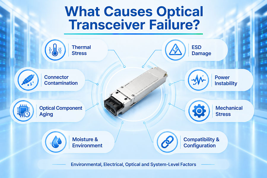
Optical transceiver reliability depends on the coordinated operation of optical components, electronic circuits, thermal management systems, firmware, and fiber connections. A failure in any one of these areas can interrupt data transmission, reduce link stability, or cause a complete loss of communication. In high-speed Ethernet and InfiniBand networks, even intermittent transceiver faults can affect link negotiation, error rates, and overall network availability.
Not every link failure means that the optical module itself is defective. Contaminated connectors, incompatible host configurations, damaged fiber, excessive insertion loss, and switch-side problems can produce similar symptoms. Identifying the actual cause requires checking the optical module alongside the entire transmission path.
1. Optical Transceiver Failure: Common Symptoms
Optical transceiver problems can appear in several ways. Some faults cause an immediate link failure, while others develop gradually and produce intermittent errors or unstable performance.
| Symptom | Possible Cause | Typical Diagnostic Direction |
|---|---|---|
| Link remains down | Module incompatibility, electrical interface fault, damaged fiber, or no optical output | Check module recognition, port status, TX output, and fiber continuity |
| Low received optical power | Dirty connectors, fiber loss, weak transmitter, or excessive link attenuation | Inspect the optical path and compare RX power with module specifications |
| High BER or packet errors | Signal degradation, unstable laser output, reflections, or signal integrity problems | Review optical levels, FEC statistics, and host interface diagnostics |
| Intermittent link disconnections | Thermal instability, poor contact, unstable power, or fiber movement | Check temperature, port logs, electrical contacts, and cable routing |
| Module not recognized | Compatibility restrictions, EEPROM communication problems, or host port faults | Check vendor identification, module information, and switch compatibility |
| High module temperature | Insufficient airflow, high ambient temperature, or excessive power consumption | Review temperature readings and equipment cooling conditions |
Accurate diagnosis starts with identifying whether the fault follows the transceiver, the host port, or the fiber connection. Replacing components without isolating the problem can increase troubleshooting time and introduce additional variables.
2. Overheating and Poor Thermal Management
Excessive temperature is one of the important environmental factors affecting optical transceiver reliability. High-speed modules contain laser drivers, receivers, digital signal processors, and other electronic components that generate heat during operation.
When the operating temperature exceeds the module's specified range, several performance problems may occur:
Laser output power may become unstable or drift from its expected operating level.
Receiver sensitivity and analog circuit performance may deteriorate.
DSP operation and signal processing reliability may be affected.
Temperature-related protection mechanisms may reduce performance or shut down the module.
Long-term exposure to excessive heat can accelerate component aging.
Thermal problems are particularly relevant in densely populated 400G, 800G, and 1.6T switch platforms. High port density, limited airflow, blocked ventilation paths, and inadequate rack cooling can create localized hot spots around transceiver cages.
Monitoring digital diagnostic monitoring (DDM) or digital optical monitoring (DOM) information helps identify abnormal temperature trends. Engineers should check the module temperature against its specified operating limits rather than applying one universal temperature threshold to every module.
3. Electrical Overload and Power Supply Problems
An optical transceiver relies on stable electrical power from the host device. Its internal circuits require appropriate voltage levels and current delivery to maintain laser operation, signal processing, and receiver performance.
Electrical problems may originate from the host switch, power delivery circuitry, connector contacts, or the module itself. Potential causes include:
Unstable host power supply or abnormal voltage conditions.
Damaged electrical contacts between the module and host cage.
Excessive power consumption beyond the host port's supported capacity.
Electrical noise or signal integrity problems on high-speed interfaces.
Component degradation in the module's driver, DSP, or power regulation circuits.
High-speed transceivers can have different power requirements depending on their form factor, optical reach, DSP architecture, and operating mode. An 800G or 1.6T module should therefore be evaluated against the host platform's power and thermal specifications before deployment.
4. Laser Degradation and Optical Component Aging
The transmitter section converts electrical signals into optical signals. Depending on the module design and application, it may use VCSEL, DFB, EML, or other laser technologies. These components can gradually change their operating characteristics over time.
Long-term operating stress, temperature exposure, and component aging may contribute to:
Reduced transmitter output power.
Changes in wavelength stability.
Increased noise or degraded signal quality.
Changes in extinction ratio or other transmitter characteristics.
Intermittent optical output under certain operating conditions.
Receiver components can also deteriorate. PIN and APD photodetectors, transimpedance amplifiers, and related receiver circuitry may experience changes that affect sensitivity and signal quality.
Laser degradation is not always visible through a simple link-status check. Comparing transmitter output power, receiver power, and error statistics over time provides a more useful indication of changing optical performance.
5. Fiber Connector Contamination and Physical Damage
Contamination at fiber end faces is a frequent source of optical link problems. Dust, oil, fingerprints, and other particles can obstruct the optical path, increase insertion loss, and create reflections.
Even when a transceiver is operating normally, a contaminated LC or MPO connector can cause low received power, unstable links, or elevated bit error rates.
Physical damage can create similar symptoms. Common examples include:
Scratched or damaged connector end faces.
Excessive fiber bending or crushing.
Broken or poorly terminated fiber cables.
Loose connector engagement.
Damaged adapter sleeves or fiber alignment components.
Connector inspection should be part of routine optical troubleshooting. Use an appropriate fiber inspection tool and approved cleaning equipment. Inspect before connecting, and avoid touching exposed fiber end faces.
For more reliable operation, fiber routing should also respect the cable manufacturer's minimum bend-radius requirements. Tight bends and mechanical stress can increase attenuation or cause intermittent transmission faults.
6. Incorrect Optical Power Budget and Link Design
An optical transceiver must operate within the optical power range supported by its receiver. A link with excessive attenuation may deliver insufficient optical power, while an overly strong received signal can also exceed the receiver's supported input range.
The optical power budget is determined by the transmitter output, receiver sensitivity, and losses across the transmission path. Fiber length, connector pairs, splices, patch panels, and other passive components all contribute to total link loss.
| Optical Link Condition | Potential Effect | Recommended Check |
|---|---|---|
| Received power below receiver sensitivity | Link failure or high error rate | Measure end-to-end attenuation and inspect connectors |
| Received power above maximum input level | Receiver overload or degraded signal performance | Check transmitter output and link attenuation |
| Excessive insertion loss | Reduced optical margin | Test fiber, connectors, patch panels, and splices |
| High return loss or reflections | Potential signal degradation | Inspect connector quality and optical path design |
| Incorrect fiber type or wavelength | Excessive loss or unsupported transmission | Verify module specifications and fiber compatibility |
Engineers should calculate the complete link budget instead of relying only on the nominal transmission distance printed on a transceiver specification sheet. Actual performance depends on the installed fiber plant and its optical characteristics.
7. Module Compatibility and Host Configuration Errors
A transceiver can be electrically and optically functional but still fail to establish a link because the host device does not support its configuration. Compatibility involves more than matching the physical connector or module form factor.
Important compatibility factors include:
Form factor: The module must fit the supported cage and mechanical interface, such as SFP28, QSFP28, QSFP-DD, OSFP, or QSFP112.
Data rate: The host port must support the module's operating rate and lane configuration.
Protocol: Ethernet and InfiniBand applications may require different host configurations and supported operating modes.
Wavelength and fiber: Both ends of the link must use compatible optical specifications and fiber types.
Firmware and coding: Host software may apply module recognition or compatibility restrictions.
FEC settings: The two endpoints must use compatible forward error correction configurations where required.
For example, two 400G modules may have the same physical form factor but use different optical lane architectures, wavelengths, reach specifications, or host interface requirements. Physical insertion alone does not guarantee a working link.
Before deployment, verify the module's datasheet, host-device compatibility, port configuration, and the specifications of the remote transceiver.
8. ESD Damage and Improper Handling
Electrostatic discharge (ESD) can damage sensitive electronic components inside an optical transceiver. The damage may be immediate or may weaken a component and lead to an intermittent fault later.
Transceivers contain semiconductor devices and high-speed electronic circuits that require appropriate electrostatic protection during manufacturing, testing, storage, and installation.
Common handling-related risks include:
Installing or removing modules without suitable ESD precautions.
Touching exposed electrical contacts.
Storing modules outside protective ESD packaging.
Placing modules on unsuitable work surfaces.
Using excessive mechanical force during insertion or removal.
Use ESD-safe workstations, appropriate grounding procedures, and protective packaging. Keep dust caps installed when optical ports are not connected, and handle modules by their designated body rather than exposed contacts or optical interfaces.
9. Manufacturing Defects and Component Quality Issues
Although many optical link failures originate from external conditions, manufacturing and component-quality issues can also affect transceiver reliability. Optical modules combine multiple precision components, and performance depends on their integration and verification.
Potential quality-related problems include:
Inconsistent laser or photodetector performance.
Defects in driver, receiver, or DSP circuitry.
Optical alignment deviations.
Weak solder joints or unreliable electrical connections.
EEPROM programming or identification errors.
Insufficient thermal or high-speed signal integrity validation.
Reliable manufacturing requires component screening, optical performance measurement, electrical testing, temperature verification, and host-platform interoperability testing. Testing should reflect the intended application and operating conditions rather than relying only on basic module recognition.
10. How to Diagnose a Faulty Optical Transceiver
A structured troubleshooting process helps distinguish module faults from problems in the host device, fiber plant, and remote endpoint. The following workflow provides a practical starting point for network engineers.
| Step | Diagnostic Action | What to Identify |
|---|---|---|
| 1. Check port status | Review switch interface status, alarms, and event logs | Whether the port is administratively disabled, unsupported, or experiencing link faults |
| 2. Read module diagnostics | Check temperature, voltage, TX power, and RX power | Abnormal operating conditions or optical levels outside specifications |
| 3. Inspect connectors | Inspect and clean both ends of the fiber connection | Contamination, scratches, or poor connector engagement |
| 4. Test the fiber path | Use suitable optical test equipment | Excessive attenuation, breaks, or other fiber-path issues |
| 5. Verify compatibility | Check module specifications and host configuration | Data rate, protocol, wavelength, FEC, and coding compatibility |
| 6. Isolate components | Use known-good compatible components in a controlled test | Whether the fault follows the module, port, or fiber path |
| 7. Review error statistics | Monitor BER, FEC counters, and interface errors | Whether the link is stable after corrective action |
When swapping components for diagnosis, change one variable at a time and use equipment known to be compatible with the host. Record the original diagnostic readings before making changes so that the results can be compared accurately.
11. How to Prevent Optical Transceiver Failure
Preventive maintenance reduces avoidable faults and helps maintain stable optical connectivity. A practical maintenance program should cover the module, host equipment, fiber infrastructure, and installation environment.
Maintain proper cooling: Keep ventilation paths clear and operate modules within their specified temperature ranges.
Inspect fiber connectors: Follow inspection and cleaning procedures before connecting or reconnecting optical cables.
Use compatible equipment: Confirm host support, data rate, protocol, wavelength, and FEC requirements before installation.
Follow ESD procedures: Use suitable protective equipment and packaging during handling and storage.
Monitor DDM data: Track temperature, voltage, TX power, and RX power for abnormal changes.
Protect fiber routing: Avoid excessive bending, pulling, crushing, and repeated mechanical stress.
Keep maintenance records: Record module serial numbers, installation dates, diagnostic readings, and failure events.
Validate new deployments: Test link performance and interoperability before production use.
For large data center networks, automated monitoring can help identify gradual changes before they develop into service-impacting faults. Historical optical power and temperature data are particularly useful when investigating intermittent problems.
12. Optical Transceiver Reliability Across High-Speed Applications
As network speeds increase, transceiver design becomes more demanding. Higher data rates introduce tighter electrical signal integrity requirements, more complex signal processing, and greater thermal management challenges.
In 100G and 400G deployments, engineers must consider optical reach, modulation format, lane configuration, and FEC requirements. At 800G and 1.6T, host electrical interfaces, DSP power consumption, cooling capacity, and port density become increasingly important design considerations.
Different optical applications also have distinct failure risks:
| Application | Key Reliability Considerations |
|---|---|
| Short-reach multimode links | Connector cleanliness, fiber type, polarity, and lane alignment |
| Single-mode data center links | Optical power budget, wavelength compatibility, and fiber attenuation |
| Long-distance optical links | Receiver sensitivity, dispersion, optical amplification, and link engineering |
| High-density 800G and 1.6T systems | Thermal performance, host compatibility, electrical signal integrity, and power delivery |
| Industrial optical networks | Operating temperature, vibration, environmental protection, and mechanical stability |
Reliability planning should therefore be application-specific. A module that performs well in a controlled data center environment may require different environmental qualifications for industrial or outdoor network deployments.
13. C-LIGHT Optical Transceiver Solutions and Quality Support
Stable optical connectivity requires transceivers that match the network architecture, host platform, and operating environment. C-LIGHT provides optical connectivity solutions across data center, enterprise, telecom, and high-performance computing applications.
Relevant product categories include:
100G optical transceivers: QSFP28 modules for short-reach and single-mode optical connections.
400G optical transceivers: QSFP-DD and OSFP solutions for data center interconnects and high-bandwidth switching.
800G optical transceivers: High-density solutions including SR8 and 2FR4 application categories.
1.6T optical connectivity: Next-generation OSFP-based solutions for emerging high-bandwidth infrastructure.
DAC and AEC assemblies: Short-distance electrical connectivity for switch, server, and accelerator interconnections.
Optical passive components: Fiber connectivity and MPO/MTP solutions for structured optical cabling.
Product selection should be based on the required transmission distance, fiber type, host compatibility, power consumption, thermal conditions, and application protocol. For high-speed deployments, checking the complete link configuration before installation helps reduce compatibility-related faults and unnecessary replacement costs.
C-LIGHT can support optical connectivity requirements across different data rates, form factors, and network applications. Contact our team to discuss module specifications, host compatibility, and deployment requirements.
14. Conclusion
Optical transceiver failure can result from multiple factors, including overheating, electrical instability, laser aging, connector contamination, fiber damage, incorrect optical power budgets, compatibility problems, ESD exposure, and component-quality issues. Similar symptoms can originate from different parts of the network, so replacing a module should not be the first response to every link failure.
A reliable troubleshooting process combines DDM monitoring, connector inspection, optical power measurement, host compatibility verification, and controlled component isolation. With appropriate installation practices, thermal management, and preventive maintenance, network operators can reduce avoidable failures and improve the long-term stability of optical communication systems.
 >

 >
 >
 >
 >
 >
 >
 >