TEL:+86 132 6656 7067





A modern data center fabric depends on two distinct switching roles to connect servers and move traffic between racks. Leaf switches sit at the edge of the fabric, providing connectivity for servers, storage and network services. Spine switches form the high-speed transit layer, forwarding traffic between leaf switches through multiple routed paths.
Although spine and leaf switches may use similar hardware platforms, they are not interchangeable in a conventional two-tier spine-leaf design. Their port assignments, connectivity patterns, routing responsibilities and capacity requirements are different. A leaf switch connects endpoint devices and uplinks to every spine, while a spine switch connects to the leaf layer and normally does not connect directly to servers.
Understanding these roles is essential when designing data center bandwidth, selecting optical transceivers, planning redundancy and expanding network capacity. The distinction becomes especially important in environments with high east-west traffic, distributed applications, virtualization and AI computing clusters.
1. What Is a Leaf Switch?
A leaf switch is the access layer device in a spine-leaf network. It connects servers, storage systems, hypervisors, firewalls, load balancers and other endpoint devices to the data center fabric. In many deployments, leaf switches are installed at the top of each rack and are therefore also described as Top-of-Rack (ToR) switches.
A leaf switch provides downlink ports for connected devices and uplink ports for connections to the spine layer. Every leaf in a conventional two-tier fabric connects to every spine switch, creating multiple possible paths for traffic to reach other leaves.
Leaf switches commonly perform several functions:
Server connectivity: Provide Ethernet connections for physical servers, virtualization hosts and compute nodes.
Storage connectivity: Connect storage arrays and distributed storage systems to the network fabric.
Network access: Provide attachment points for firewalls, load balancers and other network services where the design requires them.
Layer 2 and Layer 3 functions: Support VLANs, gateway functions, routing and other access-edge services according to the fabric design.
Traffic entry into the fabric: Forward traffic from connected endpoints toward the appropriate spine paths.
Network segmentation: Participate in tenant, subnet and virtual network separation, including VXLAN EVPN deployments.
In a routed leaf-spine architecture, the leaf commonly acts as the Layer 3 boundary for connected server subnets. It can provide default gateway services and route traffic into the fabric. The exact gateway and overlay functions depend on the selected design.
2. What Is a Spine Switch?
A spine switch is the high-speed transit device in the upper layer of a two-tier spine-leaf fabric. Its primary responsibility is to interconnect leaf switches and forward traffic between them. Unlike a leaf switch, a conventional spine switch does not normally connect directly to servers or storage endpoints.
Every leaf switch connects to every spine switch in the fabric. When a server connected to one leaf communicates with a server connected to another leaf, traffic normally travels through one spine switch before reaching the destination leaf.
Spine switches are typically designed with substantial switching capacity and a large number of high-speed ports. They provide the transit bandwidth needed for communication across racks and help distribute traffic across multiple equal-cost paths.
Their main responsibilities include:
Inter-leaf forwarding: Carry traffic between different leaf switches.
Fabric bandwidth: Provide high-capacity connections between the leaf layer and the rest of the network.
ECMP routing: Support multiple equal-cost routed paths so traffic can use available spine connections.
Path redundancy: Provide alternative transit paths if a spine switch or an individual link becomes unavailable.
Predictable topology: Maintain a consistent leaf-to-spine connection pattern as the fabric grows.
In a conventional Layer 3 spine-leaf design, spine switches focus on IP forwarding rather than endpoint access or application services. This separation helps keep the fabric structure consistent and simplifies horizontal expansion.
3. How Spine and Leaf Switches Connect
The defining feature of a two-tier spine-leaf network is that every leaf switch connects to every spine switch. Spine switches provide the transit paths between leaves, while leaf switches connect the endpoints to the fabric.
Typical spine-leaf topology
Spine Layer: Spine 1 | Spine 2 | Spine 3 | Spine 4
Each leaf connects to all four spine switches.
Leaf Layer: Leaf 1 | Leaf 2 | Leaf 3 | Leaf 4
Servers, storage and network services connect to the leaf layer.
Consider two servers connected to different leaf switches. The source server sends traffic to its local leaf, which forwards the packet toward an available spine. The spine forwards it to the destination leaf, and the destination leaf delivers it to the receiving server.
If both servers connect to the same leaf, their traffic may be switched locally without passing through the spine layer. This distinction affects how much traffic actually consumes the fabric uplink bandwidth.
Spine switches are generally not interconnected with one another in a conventional two-tier Layer 3 fabric. Instead, the leaf-to-spine routed links provide the paths required for inter-leaf communication.
4. Main Differences Between Spine and Leaf Switches
Both devices are Ethernet switches, but their roles within the fabric are different. A leaf switch is optimized for endpoint attachment and uplink connectivity, while a spine switch is designed to provide high-capacity transit between leaves.
| Feature | Leaf Switch | Spine Switch |
|---|---|---|
| Network position | Access or edge layer | Fabric transit or backbone layer |
| Primary role | Connect servers, storage and network services | Interconnect leaf switches and forward traffic across the fabric |
| Server connections | Directly connects to servers and endpoint devices | Normally does not connect directly to servers |
| Spine connectivity | Connects to every spine switch | Connects to every leaf switch |
| Traffic direction | Receives endpoint traffic and forwards it locally or into the fabric | Forwards traffic between different leaves |
| Port allocation | Downlinks for endpoints and uplinks for spines | Primarily ports for leaf-facing connections |
| Routing role | Often provides endpoint gateways and routes traffic into the fabric | Provides routed transit between leaf switches |
| Common deployment | Top-of-Rack or End-of-Row access | Centralized fabric switching layer |
| Capacity planning | Server port density, downlink bandwidth and uplink oversubscription | Aggregate fabric bandwidth, port count and switching capacity |
| Expansion | Added when more racks, endpoints or access ports are needed | Added when additional fabric paths or spine capacity are required |
5. Traffic Flow Between Spine and Leaf Switches
Traffic flow depends on where the communicating devices are connected. In a spine-leaf fabric, communication within the same leaf can remain local, while communication between different leaves normally traverses one spine.
For example, when a server in Rack A communicates with a server in Rack B, the traffic enters the leaf switch in Rack A. That leaf selects an available spine path, and the selected spine forwards the packet to the leaf connected to Rack B.
This structure creates a predictable path between racks. With multiple spine switches, the network can provide several equal-cost paths between leaf switches, assuming the routing and link configuration support ECMP.
| Traffic Scenario | Traffic Path | Spine Involvement |
|---|---|---|
| Server to server on the same leaf | Server → Leaf → Server | Normally not required |
| Server to server on different leaves | Server → Leaf → Spine → Leaf → Server | One spine in the typical two-tier path |
| Server to external network | Server → Leaf → Border Leaf or gateway path → External network | Depends on the external connectivity design |
| Traffic to a shared service | Server → Leaf → Service attachment or service leaf | Depends on where the service is connected |
A spine switch does not necessarily inspect application traffic or provide firewall services. In many designs, those functions are handled by dedicated appliances or service platforms connected through designated leaf switches.
6. Bandwidth and Oversubscription
Leaf and spine switches have different bandwidth planning requirements. Leaf switches must provide enough server-facing capacity while maintaining sufficient uplink bandwidth to carry traffic toward other racks. Spine switches must provide enough aggregate capacity to handle the traffic arriving from all connected leaves.
Consider a leaf switch with 48 server-facing ports operating at 25 Gbps each. Its total nominal downlink capacity is:
This represents the aggregate nominal server-facing port capacity, not guaranteed application throughput.
If the same leaf has six 100 Gbps uplinks to the spine layer, its total nominal uplink capacity is 600 Gbps. The downlink-to-uplink ratio is therefore 2:1.
This is a nominal 2:1 oversubscription ratio. It does not mean that every workload will experience congestion, because actual traffic depends on server utilization, communication patterns and traffic distribution. However, applications with heavy simultaneous inter-rack communication may require more uplink capacity.
Spine capacity must also be considered across the complete fabric. Adding more leaf switches increases the number of connections and the aggregate traffic that the spine layer may need to carry. A fabric can have sufficient individual link speeds but still become constrained by total switch capacity or port availability.
7. ECMP and Redundant Network Paths
Equal-Cost Multipath routing is a fundamental feature of many Layer 3 spine-leaf networks. Since each leaf connects to multiple spine switches, the routing system can install multiple equal-cost routes toward destinations behind other leaves.
ECMP allows traffic to be distributed across these paths using a hashing method based on packet or flow information. This can improve aggregate network utilization and reduce dependence on a single spine switch.
If one spine switch or one leaf-to-spine link fails, the routing system can use remaining eligible paths after detecting and responding to the failure. The actual recovery time depends on routing configuration, failure detection, platform behavior and available capacity.
Leaf redundancy is also important. Critical servers may connect to a pair of leaf switches using supported multihoming technologies such as MLAG or EVPN multihoming. This allows connectivity to remain available if one leaf or one server-facing link becomes unavailable, subject to the design and remaining network capacity.
8. Port Density and Optical Connectivity
The port requirements of spine and leaf switches are different because they connect to different parts of the network. Leaf switches need a combination of server-facing ports and spine-facing uplinks. Spine switches primarily need enough high-speed ports to connect to all leaves.
As data center Ethernet speeds increase, optical interconnect selection becomes an important part of the fabric design. A leaf switch may use 10G, 25G, 50G or 100G server-facing connections, depending on the platform and workload. Its uplinks may operate at 100G, 200G, 400G or higher speeds. Spine switches commonly use high-speed optical ports to aggregate traffic from multiple leaves.
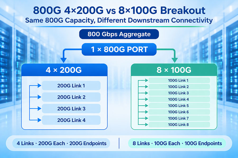
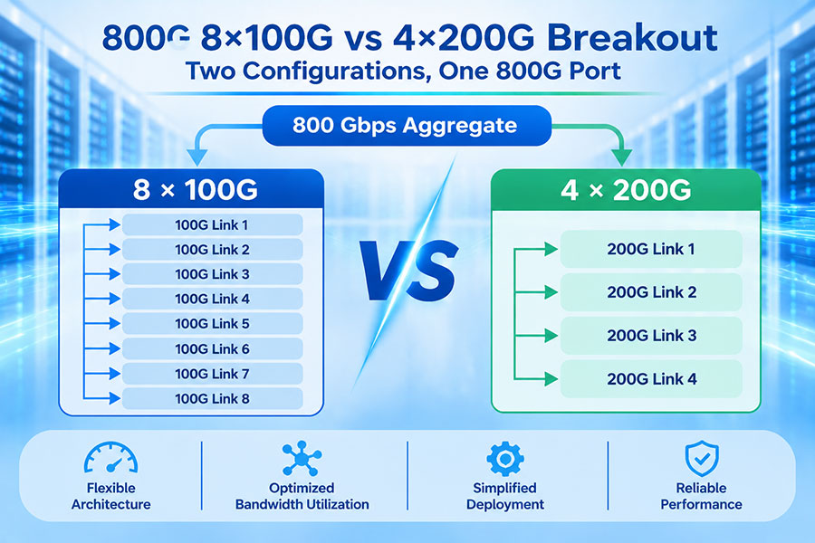
The exact combination depends on switch generation, port density, breakout support, available optics and the target fabric bandwidth. A 400G port, for example, may support different breakout configurations where the switch and transceiver specifications permit them.
C-LIGHT's Optical Transceiver portfolio includes optical connectivity options for different data rates, wavelengths, fiber types and transmission distances. The appropriate module should be selected according to the switch port, optical reach, fiber infrastructure, connector interface and link budget.
For short connections, DAC or AOC solutions may also be suitable where supported by the switch platform and distance requirements. Longer inter-rack or inter-room links generally require optical transceivers and compatible fiber assemblies.
9. Spine Switch vs Leaf Switch in AI Data Centers
AI data centers place particularly demanding requirements on the network fabric. Distributed training and inference workloads can generate substantial traffic between GPUs, servers and storage systems. The leaf layer provides connectivity for compute nodes, while the spine layer carries traffic between racks and other parts of the fabric.
In Ethernet-based AI networks, leaf-spine topology can provide multiple routed paths between server-facing switches. However, the topology alone does not guarantee the performance required by large distributed training jobs. Link capacity, congestion management, load balancing, network interface capabilities and application communication patterns all influence performance.
AI infrastructure may use 400G and 800G Ethernet connections, with 1.6T connectivity emerging in newer high-bandwidth designs. These higher speeds increase the importance of optical module power, thermal management, fiber infrastructure and switch port density.
It is also important to distinguish Ethernet spine-leaf networks from InfiniBand fabrics. Both can use multi-stage switching architectures, but their protocols, management models and congestion-control mechanisms differ. A network design should be evaluated against the actual compute platform and communication technology.
10. How to Choose the Right Spine and Leaf Switches
Spine and leaf switches should be selected as components of one fabric rather than as isolated devices. Port compatibility, aggregate bandwidth, routing features, optical support and expansion capacity must be considered together.
For leaf switches, review:
Number and speed of server-facing ports.
Available uplink ports and supported breakout configurations.
Switching capacity and packet-forwarding performance.
Layer 2 and Layer 3 feature support.
VXLAN EVPN, gateway and multihoming capabilities where required.
Server NIC compatibility and port-speed requirements.
Power consumption, airflow and rack installation constraints.
For spine switches, review:
Number of leaf-facing ports and supported port speeds.
Aggregate switching capacity and forwarding performance.
ECMP scale and routing table capacity.
Buffer and congestion-management capabilities relevant to the workload.
Optical module compatibility and link-distance requirements.
Power, cooling and rack-density requirements.
Capacity for future leaf additions and fabric expansion.
Both layers should use compatible routing protocols, software features and operational procedures. The selected design must also account for failure scenarios, maintenance requirements and the amount of bandwidth available after a link or switch becomes unavailable.
11. Conclusion
Spine and leaf switches perform complementary roles in a modern data center fabric. Leaf switches connect servers, storage and network services to the network, while spine switches provide high-speed routed paths between leaf switches.
The leaf layer determines endpoint connectivity, server port density and much of the access-side bandwidth requirement. The spine layer determines how traffic is carried between leaves and how much aggregate transit capacity the fabric can support.
A balanced spine-leaf design requires careful planning of downlink and uplink speeds, oversubscription, ECMP paths, optical connectivity, redundancy and future expansion. Selecting both switch types as part of one coordinated architecture helps create a scalable and reliable data center network.
For optical connectivity requirements and product support, Contact C-LIGHT.
 >

 >
 >
 >
 >
 >
 >
 >