TEL:+86 132 6656 7067





As network equipment moves to 100GbE and 400GbE interfaces built around 112G-class electrical lanes, compact pluggable form factors are becoming increasingly important to switch design. SFP112 and QSFP112 address different bandwidth requirements within this transition. SFP112 provides a compact single-lane interface for 100GbE, while QSFP112 combines four high-speed lanes in a single module to support 400GbE.
Their port-density characteristics therefore need to be assessed from two perspectives: the number of physical ports that fit on a switch front panel and the aggregate bandwidth delivered by those ports. SFP112 has a smaller module profile, which can support compact single-port layouts. QSFP112 occupies a larger port position but delivers four times the nominal data rate of a 100G SFP112 module. The best choice depends on whether the equipment design prioritizes individual port count, bandwidth per port, or total front-panel throughput.
1. SFP112 and QSFP112: Different Lane Configurations
The number 112 in both form-factor names refers to the high-speed electrical lane generation, not the total data rate of every module. This distinction is essential when evaluating port density.
A typical 100G SFP112 optical transceiver uses one electrical lane operating at approximately 112Gbps signaling with PAM4 modulation to carry a nominal 100GbE data rate. QSFP112 uses four electrical lanes at the same lane generation, supporting a nominal aggregate data rate of 400Gbps.
| Parameter | SFP112 | QSFP112 |
|---|---|---|
| Typical Ethernet rate | 100GbE | 400GbE |
| Electrical lane count | 1 | 4 |
| Electrical lane generation | 112G-class | 112G-class |
| Modulation | PAM4 | PAM4 |
| Module size category | Compact SFP form factor | Four-lane QSFP form factor |
| Nominal bandwidth per port | 100Gbps | 400Gbps |
| Typical application | 100GbE switch and router links | 400GbE aggregation, AI and data center links |
2. Physical Module Size and Front-Panel Layout
SFP112 follows the compact SFP mechanical family. Its smaller form factor makes it suitable for switch designs that need a high number of individual optical interfaces across a limited front-panel area. A single-lane architecture also keeps the host electrical interface relatively straightforward compared with a four-lane module.
QSFP112 uses a wider four-lane package. Each module carries four electrical channels and supports a higher aggregate data rate. The larger port position means that a switch designer must allocate more front-panel space to each interface than to an SFP112 port.
However, module width alone does not establish the maximum number of ports in a switch. Cage spacing, connector access, PCB routing, airflow, power delivery and chassis dimensions all affect the final layout. A real port-density assessment must use the equipment manufacturer's published front-panel configuration rather than module dimensions in isolation.
3. Bandwidth Density: 100G SFP112 vs 400G QSFP112
QSFP112 provides four times the nominal bandwidth of SFP112 per module. This makes it attractive when the objective is to increase aggregate switch throughput without assigning a separate physical port to every 100G connection.
SFP112 can still provide a higher count of individual interfaces in a given front-panel area because of its smaller package. Whether that results in more total bandwidth depends on the actual port layout and the number of modules that can be installed.
The following examples show the bandwidth arithmetic for illustrative port counts. They are not claims about the maximum port count of a particular switch model.
| Port Configuration | Port Rate | Aggregate Bandwidth |
|---|---|---|
| 32 × SFP112 | 100Gbps | 3.2Tbps |
| 48 × SFP112 | 100Gbps | 4.8Tbps |
| 8 × QSFP112 | 400Gbps | 3.2Tbps |
| 12 × QSFP112 | 400Gbps | 4.8Tbps |
| 16 × QSFP112 | 400Gbps | 6.4Tbps |
These examples illustrate an important design trade-off: 32 SFP112 ports and 8 QSFP112 ports both provide 3.2Tbps of nominal aggregate bandwidth. The QSFP112 configuration reaches that bandwidth with fewer physical ports, while SFP112 offers more individual connection points. The actual chassis area and cooling requirements must be considered before deciding which layout is more space-efficient.
4. Thermal Management and Power Considerations
Port density is closely connected to thermal design. Increasing the number of optical modules in a switch raises the total heat load around the front panel. Even when each module has a relatively low individual power rating, a fully populated system can require substantial airflow and carefully controlled thermal paths.
SFP112's single-lane architecture can support compact 100G optical designs. The module's actual power consumption depends on its optical engine, laser technology, reach, DSP or retiming requirements, and implementation. A smaller package should not automatically be assumed to consume less power than every QSFP112 design.
QSFP112 integrates four high-speed lanes in one module. Its power and cooling requirements depend on the optical configuration and module power class. The QSFP112 MSA defines thermal requirements and includes mechanical variants intended to support different cooling approaches. Higher-power implementations may require additional space or heatsink provisions.
For system designers, the important metric is not only power per transceiver but also total optical power per front-panel area. Switch airflow, cage design, heatsink contact, inlet temperature and adjacent-module operation should all be assessed at full port population.
5. Fiber Interfaces and Transmission Applications
SFP112 and QSFP112 serve different link-capacity requirements, and their optical interfaces reflect those differences.
100G SFP112 modules commonly use duplex LC connectivity for single-mode applications such as DR1, FR1 and LR1. These configurations support point-to-point 100GbE links over different distances, depending on the optical specification and fiber plant.
400G QSFP112 modules can use parallel-fiber MPO interfaces or duplex LC interfaces, depending on the optical implementation. DR4 and SR4 designs use multiple optical lanes, while FR4 and LR4 designs use wavelength-division multiplexing to support higher aggregate rates over duplex fiber.
Choosing between these modules therefore involves more than port density. Engineers must also consider the available fiber infrastructure, connector type, optical reach, patch-panel capacity and the number of fibers required per link.
6. Network Architecture and Deployment Scenarios
SFP112 is well suited to network designs that need a large number of independent 100GbE connections. It can be useful for server-facing links, leaf switches, compact aggregation platforms and environments where each device or connection requires a dedicated 100G interface.
QSFP112 is designed for 400GbE connectivity. It can serve as a high-capacity switch uplink, spine connection, aggregation interface or interconnect for high-performance computing and AI infrastructure. Consolidating multiple 100G connections into fewer 400G ports can simplify the physical layout and reduce the number of individual links required for a given aggregate bandwidth.
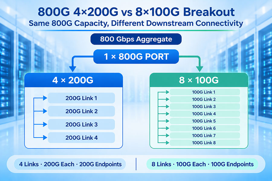
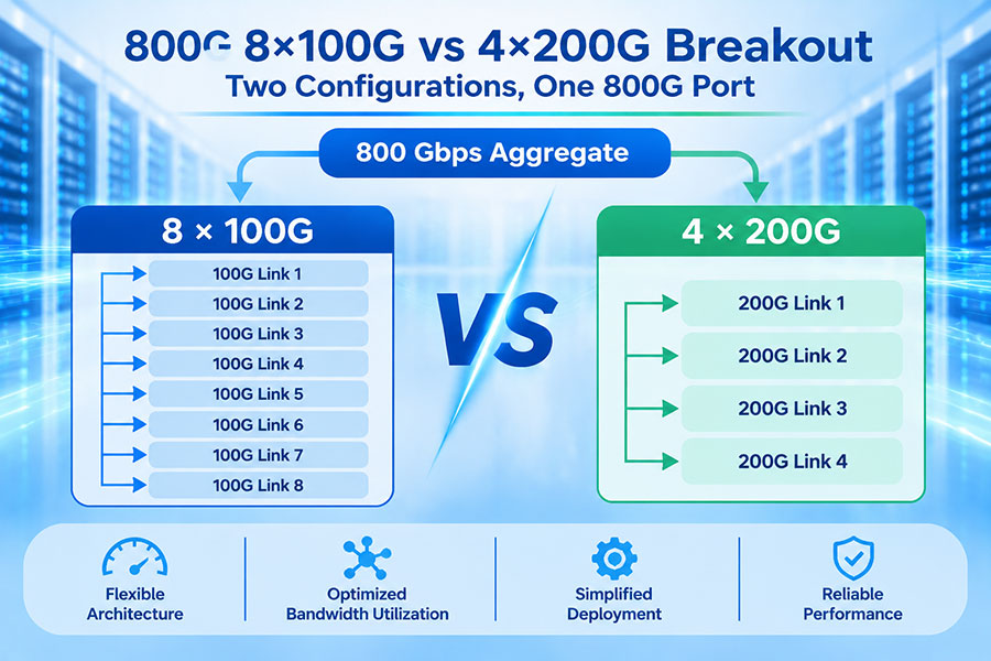
Breakout support can add flexibility to QSFP112 deployments. Depending on the switch ASIC, port configuration and supported optical or cable type, a 400G port may be divided into multiple lower-speed connections. This can help connect 400G-capable switching equipment to devices that still use 100G interfaces. The available breakout modes must be confirmed for the exact switch and transceiver combination.
7. Compatibility and Migration Planning
SFP112 and QSFP112 use different mechanical interfaces and are not physically interchangeable. A switch designed for SFP112 requires the corresponding SFP112 cage and electrical interface, while QSFP112 requires a QSFP112-compatible host port.
Although both use 112G-class electrical lanes, that does not mean a 100G SFP112 module can operate in a QSFP112 port or that the two form factors share the same host interface. Platform support, module management, firmware, electrical signaling and optical specifications must all match.
For migration projects, confirm the switch model, supported port speed, host interface generation, module power class, optical standard and firmware requirements. If a 400G QSFP112 port is intended to connect to four 100G endpoints, verify that the switch supports the required breakout configuration and that the selected optical or cabling solution supports the intended topology.
8. C-LIGHT 100G SFP112 and 400G QSFP112 Optical Transceivers
C-LIGHT provides both compact 100G SFP112 and four-lane 400G QSFP112 optical transceiver solutions, addressing different port-density and bandwidth requirements.
The C-LIGHT 100G SFP112 optical transceiver portfolio includes single-mode 1310nm options for 500m, 2km and 10km transmission. These modules use duplex LC connectivity and are designed for 100GbE links where compact module size and individual port availability are important.
The C-LIGHT 400G QSFP112 optical transceiver portfolio includes SR4, DR4, FR4 and LR4 configurations. Listed transmission options include 50m, 100m, 500m, 2km and 10km, depending on the model. The modules use four 112G-class electrical channels to deliver nominal 400GbE connectivity.
For additional form factors and optical interfaces, visit the C-LIGHT Optical Transceiver product category. Before selecting a module, verify the host switch model, supported data rate, fiber type, connector, optical reach and required operating temperature.
9. Selecting the Right Form Factor for Port Density
SFP112 is a practical choice when a network requires numerous compact 100GbE interfaces. Its single-lane architecture and smaller package can help equipment manufacturers build front panels with a high number of individual ports. It is especially relevant when the network topology requires many separate 100G connections rather than a smaller number of higher-capacity links.
QSFP112 is better suited to applications that prioritize 400GbE per port and higher aggregate bandwidth from each physical interface. It can reduce the number of ports and optical links needed to deliver a given amount of bandwidth, although its larger module footprint and thermal requirements must be included in the chassis design.
The selection should be based on the target switch architecture, port count, total switching capacity, breakout requirements, fiber infrastructure and cooling budget. A smaller transceiver does not always produce the highest system bandwidth density, just as a higher-speed module does not always produce the greatest number of individual ports.
10. Conclusion
SFP112 and QSFP112 use the same 112G-class electrical lane generation but serve different bandwidth levels. SFP112 provides a compact single-lane 100G interface, while QSFP112 combines four lanes to deliver 400G in one module.
For physical port count, SFP112's smaller package can support compact front-panel arrangements. For bandwidth per port and aggregate throughput, QSFP112 provides a fourfold increase over a 100G SFP112 interface. The best option depends on whether the network needs more independent connections or greater bandwidth from each port.
For 100G SFP112 and 400G QSFP112 optical transceiver requirements, visit C-LIGHT optical networking products or Contact C-LIGHT for technical assistance.
 >

 >
 >
 >
 >
 >
 >
 >