TEL:+86 132 6656 7067





As switch bandwidth increases, the amount of network capacity that can be installed within a fixed rack space becomes a major design consideration. High-density optical module deployments help operators increase front-panel bandwidth and reduce the number of physical ports required for a given traffic capacity. Standard optical module configurations, meanwhile, remain important where equipment compatibility, deployment flexibility, power limits, and established network architectures take priority.
The distinction between high-density and standard optical modules is not defined by one universal optical specification. It is primarily a system-level design consideration involving module form factor, port spacing, electrical lane architecture, optical bandwidth, thermal performance, and the capabilities of the host switch or router.
1. What Are High-Density and Standard Optical Modules?
High-density optical modules are transceivers deployed in hardware platforms designed to provide more bandwidth or more optical interfaces within a limited front-panel area. Compact multi-lane form factors such as QSFP-DD and QSFP112-DD support high data rates while allowing network equipment manufacturers to build dense switch-port layouts. OSFP is another high-speed pluggable form factor used in demanding 400G and 800G network platforms.
Standard optical modules generally refer to conventional or lower-density port configurations, including SFP, SFP+, SFP28, QSFP+, and QSFP28 deployments. These modules cover a broad range of Ethernet and optical networking applications, from enterprise access links to data center connections and telecom infrastructure.
2. Form Factor and Port Density
Physical form factor determines how a transceiver fits into the host cage and front panel. It affects the spacing between ports, the number of modules that can be installed, electrical connectivity, and thermal design. However, a smaller module does not automatically deliver a higher data rate, and a higher data rate does not always mean that more physical ports can fit on a switch.
| Form Factor | Common Data Rate Applications | Lane Architecture | Typical Deployment Role |
|---|---|---|---|
| SFP / SFP+ | 1G / 10G | Single-lane interface | Enterprise access, aggregation, and telecom links |
| SFP28 | 25G | Single-lane interface | Server access and data center leaf connections |
| QSFP28 | 100G | Commonly 4 × 25G electrical lanes | 100G data center and backbone links |
| QSFP-DD | 400G / 800G generations | Eight electrical lanes | High-bandwidth switch and router ports |
| OSFP | 400G / 800G generations | Eight electrical lanes | High-performance data center and AI networks |
| QSFP112 | 400G applications | Commonly 4 × 100G electrical lanes | High-speed data center connectivity |
| 1.6T-class pluggable designs | 1.6T | Architecture depends on the MSA and implementation | Next-generation high-capacity switching platforms |
QSFP-DD and OSFP are both used for high-speed optical connectivity, but they are physically different. A QSFP-DD module cannot be inserted directly into an OSFP cage, and an OSFP module cannot be inserted into a QSFP-DD cage. Even when two modules support the same Ethernet optical interface, the host connector and mechanical design must match.
QSFP-DD can support backward compatibility with certain earlier QSFP-family modules when the host platform is designed to support them. This can help operators migrate from 100G or 200G equipment toward 400G and 800G systems without replacing every optical connection at once. Compatibility must still be confirmed against the switch model, port configuration, and supported module list.
3. Bandwidth Density and Network Capacity
Bandwidth density describes the aggregate data capacity available within a defined physical space, such as a switch faceplate or one rack unit. It is a more useful measure than module size alone when planning high-capacity data center networks.
For example, a switch design with 32 ports operating at 400G provides 12.8 Tbps of nominal aggregate port bandwidth. A design with 32 ports operating at 800G provides 25.6 Tbps. The physical port count remains the same, but the theoretical aggregate bandwidth doubles.
| Port Configuration | Aggregate Port Bandwidth | Design Implication |
|---|---|---|
| 32 × 100G | 3.2 Tbps | Conventional high-speed aggregation |
| 32 × 400G | 12.8 Tbps | Higher capacity with fewer physical connections than lower-rate designs |
| 32 × 800G | 25.6 Tbps | Greater bandwidth per switch port |
| 32 × 1.6T | 51.2 Tbps | Next-generation bandwidth density, subject to platform availability |
These figures are arithmetic examples based on port rate multiplied by port count. They do not represent guaranteed configurations for every switch. Actual front-panel capacity depends on the switch ASIC, chassis architecture, port layout, supported line rates, and system bandwidth.
4. Power Consumption and Thermal Management
Thermal management becomes increasingly important as more high-speed optical modules are installed in a limited space. Each transceiver generates heat from its laser, photodetector, driver, DSP, and other electronic components. When module density increases, the total heat load across the switch front panel can rise significantly.
High-speed modules may require more advanced heat-sink structures, carefully controlled airflow, and host platforms designed to support their power classes. OSFP implementations often provide thermal design options suited to demanding high-speed applications. QSFP-DD offers a more compact mechanical footprint, but the available cooling capacity and supported module power depend on the specific host design.
| Design Factor | Standard-Density Deployment | High-Density Deployment |
|---|---|---|
| Thermal load | Often easier to manage at lower aggregate port power | Requires careful evaluation of total module and switch heat |
| Airflow | Depends on chassis and module specifications | Airflow consistency becomes more critical across densely populated ports |
| Power budget | Depends on module type and port count | Must account for the combined power of all populated ports |
| Heat-sink design | May use conventional module cooling structures | May require enhanced or platform-specific thermal solutions |
| Maintenance | Module replacement and access may be less constrained | Physical access and airflow obstruction need additional attention |
High-density does not automatically mean higher power consumption per bit. A newer high-speed module may deliver more bandwidth with improved energy efficiency. The correct metric is often watts per gigabit, evaluated alongside total chassis power, cooling requirements, and actual traffic utilization.
5. Optical Reach, Fiber Interfaces, and Breakout Options
High-density and standard optical modules can support a wide range of transmission distances. Port density does not determine optical reach. Reach is determined by the optical standard, wavelength, transmitter and receiver performance, fiber type, connector losses, and link budget.
Common optical interfaces include SR for short-reach multimode links, DR for single-mode parallel-fiber connections, FR for single-mode duplex-fiber links, and LR for longer-reach single-mode applications. The exact reach and fiber requirements must be checked against the specification of each module.
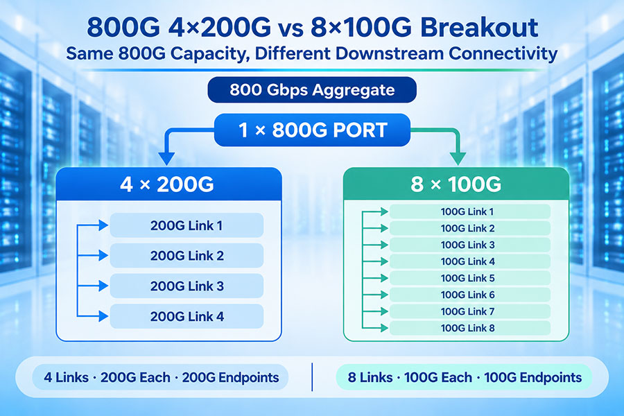
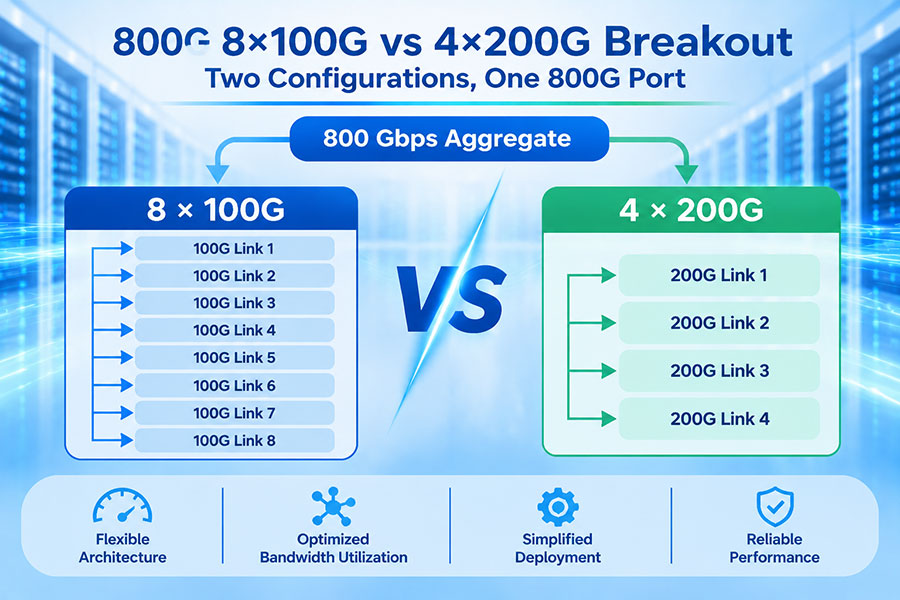
High-speed modules may also support breakout configurations. For example, an 800G switch port may be configured as two 400G connections or other supported lower-rate interfaces. A 400G port may support 2 × 200G or 4 × 100G breakout, depending on the switch, transceiver or cable, lane mapping, and software configuration.
6. High-Density vs Standard Optical Modules: Key Differences
| Evaluation Area | High-Density Optical Deployment | Standard Optical Deployment |
|---|---|---|
| Primary objective | Increase bandwidth or interface capacity within limited space | Provide connectivity suited to established equipment and network requirements |
| Typical form factors | QSFP-DD, OSFP, QSFP112-DD, and other high-speed designs | SFP, SFP+, SFP28, QSFP+, and QSFP28 |
| Bandwidth per port | Often 400G, 800G, or higher, depending on the platform | Varies from 1G to 100G and beyond |
| Front-panel capacity | Designed to increase aggregate bandwidth per unit area | Depends on the number and type of host ports |
| Thermal design | Requires close coordination between module power and chassis cooling | Depends on module power, port count, and equipment airflow |
| Network migration | May require new switches, cages, cabling, and deployment planning | Can fit existing network architectures where supported |
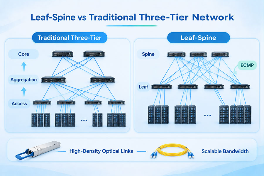
| Typical applications | AI clusters, high-capacity data centers, spine-leaf fabrics | Enterprise networks, access layers, aggregation, and existing data center links |
7. Where High-Density Optical Modules Are Used
High-density optical deployments are particularly relevant in environments where switch capacity, rack space, and interconnection bandwidth are major constraints.
AI training clusters: Large GPU and accelerator clusters require high-capacity connections between compute nodes, leaf switches, and spine switches. 400G and 800G optical interfaces help support high-bandwidth fabrics.
Hyperscale data centers: High-density switch platforms can increase aggregate front-panel capacity while controlling the physical footprint of network equipment.
High-performance computing: Parallel processing environments require high-throughput, low-latency interconnects between compute and storage systems.
Data center interconnection: High-speed optical modules support links between data center locations, with the appropriate coherent or direct-detect technology selected according to reach and network design.
Core and spine networks: Higher port bandwidth can reduce the number of physical links needed for a target aggregate capacity, subject to the topology and redundancy requirements.
8. C-LIGHT Optical Transceiver Options for Different Network Densities
Network operators can select optical transceivers according to port speed, host form factor, transmission distance, fiber infrastructure, and equipment compatibility. C-LIGHT provides optical transceiver product families for different data center and network deployment requirements.
400G optical transceivers
400G QSFP-DD and OSFP modules address high-bandwidth switch and router connections. The appropriate form factor must match the host cage and platform requirements.
800G optical transceivers
800G modules are intended for high-capacity data center fabrics and next-generation switching platforms. Selection should account for optical reach, lane architecture, power class, and cooling capability.
1.6T optical connectivity
1.6T-class pluggable modules are part of the industry's next bandwidth generation. Host-platform support, mechanical specification, thermal design, and optical interface must all be verified before deployment.
High-speed active optical connectivity
For short-reach connections between switches, servers, and other data center equipment, active optical cables can provide an integrated optical link assembly.
9. How to Select the Right Optical Module Density
The choice between high-density and standard optical deployments should begin with the network's required capacity and the capabilities of the existing equipment. A higher-density solution is not automatically the most economical or technically appropriate option.
Confirm the host interface: Identify the switch or router model, port type, supported form factors, and maximum module power.
Calculate bandwidth requirements: Evaluate current traffic, expected growth, oversubscription, and the required number of uplinks.
Check optical reach: Match SR, DR, FR, LR, or coherent interfaces to the actual fiber route and link budget.
Evaluate thermal capacity: Review module power, chassis airflow, heat-sink requirements, and the total thermal load of populated ports.
Verify breakout support: Confirm supported port modes, lane mapping, cabling, and peer-device configurations.
Assess migration costs: Include switches, transceivers, fiber cabling, power, cooling, maintenance, and future upgrade requirements.
Validate interoperability: Check module coding, firmware, management interface, FEC settings, and the vendor's compatibility documentation.
For an existing 10G, 25G, or 100G network, standard SFP- and QSFP-family modules may remain the practical choice. For new 400G and 800G data center fabrics, high-density QSFP-DD or OSFP platforms can provide greater bandwidth per port and per rack unit, provided that the host equipment and cooling infrastructure support them.
10. Conclusion
High-density and standard optical module deployments serve different network design priorities. High-density platforms focus on increasing aggregate bandwidth within limited physical space, making them suitable for AI infrastructure, hyperscale data centers, and high-capacity switching. Standard optical modules continue to provide broad connectivity options for enterprise, telecom, and established data center networks.
The most effective selection is based on the complete link and equipment environment rather than form factor alone. Port capacity, optical reach, host compatibility, power consumption, thermal performance, and upgrade costs should be evaluated together. C-LIGHT supports a range of optical connectivity options for 400G, 800G, and emerging 1.6T network architectures. For module selection or deployment requirements, Contact C-LIGHT.
 >

 >
 >
 >
 >
 >
 >
 >