TEL:+86 132 6656 7067




1. What Does It Mean When an Optical Transceiver Fails to Establish a Link?
When an optical transceiver fails to establish a link, the connected switch, router, server, or other network device cannot successfully bring the optical interface into an operational state.
The failure can occur at the physical layer, optical layer, electrical interface, configuration layer, or interoperability level. A systematic troubleshooting process helps identify the actual cause instead of replacing components unnecessarily.
2. How an Optical Link Is Established
A fiber optic link requires several conditions to work together. The host device must recognize the transceiver, the electrical interface must operate correctly, the transmitter must generate an optical signal, the receiver must detect the incoming signal, and the two endpoints must use compatible parameters.
The complete path can be simplified as:
Host Port → Optical Transceiver → Fiber → Optical Transceiver → Host Port
3. Check Whether the Transceiver Is Recognized
The first troubleshooting step is to determine whether the host device recognizes the optical transceiver.
Most switches and routers provide interface commands or management information showing module presence, vendor information, temperature, voltage, optical power, and other diagnostic parameters.
If the module is not detected, investigate the physical insertion, module compatibility, coding, host-port support, and transceiver hardware before troubleshooting the fiber link itself.
4. Check the Optical Transceiver Form Factor
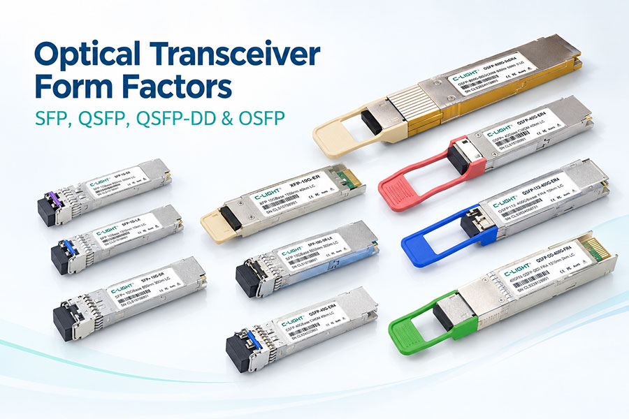
Optical transceivers are available in different form factors, including SFP, SFP+, SFP28, QSFP+, QSFP28, QSFP56, QSFP-DD, and OSFP.
The host port must support the corresponding module type. A physically compatible cage does not always guarantee electrical, firmware, or protocol compatibility.
5. Verify Transceiver Compatibility
Compatibility is one of the common causes of link establishment problems. The transceiver should be compatible with the switch, router, NIC, server, or other host platform.
Compatibility can involve form factor, data rate, electrical interface, optical specification, firmware behavior, EEPROM information, and vendor requirements.
6. Check Transceiver Coding and EEPROM Information
Some network platforms verify vendor identification or module EEPROM information before enabling an optical port.
If the module is rejected or reported as unsupported, check the platform's compatibility requirements and the module's programmed information.
7. Inspect the Optical Transceiver Physically
Remove the transceiver and inspect the module, cage, latch, connector interface, and surrounding area for visible contamination or mechanical damage.
The module should be inserted fully and securely. Poor mechanical contact can prevent the host from correctly detecting or operating the transceiver.
8. Check the Fiber Cable
A damaged, contaminated, incorrectly connected, or incompatible fiber cable can prevent an optical link from coming up.
Check the fiber type, connector type, polarity, length, bend condition, and physical routing.
9. Check Fiber Polarity
Duplex optical links require the transmitter at one end to connect to the receiver at the other end.
If the Tx and Rx paths are reversed, the two transceivers may not receive the required optical signal.
For MPO/MTP-based links, polarity becomes even more important because multiple optical channels are carried through a single connector.
10. Clean the Optical Connectors
Dust and contamination on optical connectors can increase insertion loss or block sufficient optical power from reaching the receiver.
Inspect and clean the transceiver and fiber connectors using appropriate fiber-cleaning procedures before reconnecting the link.
11. Check the Fiber Type
The optical transceiver and fiber should use compatible fiber types.
Typical combinations include multimode fiber for short-reach SR applications and single-mode fiber for DR, FR, LR, ER, and other longer-reach applications.
Using an inappropriate fiber type can result in excessive loss or an optical interface that does not meet the intended operating conditions.
12. Check the Wavelength
The transmitter wavelength must be compatible with the receiver and optical path.
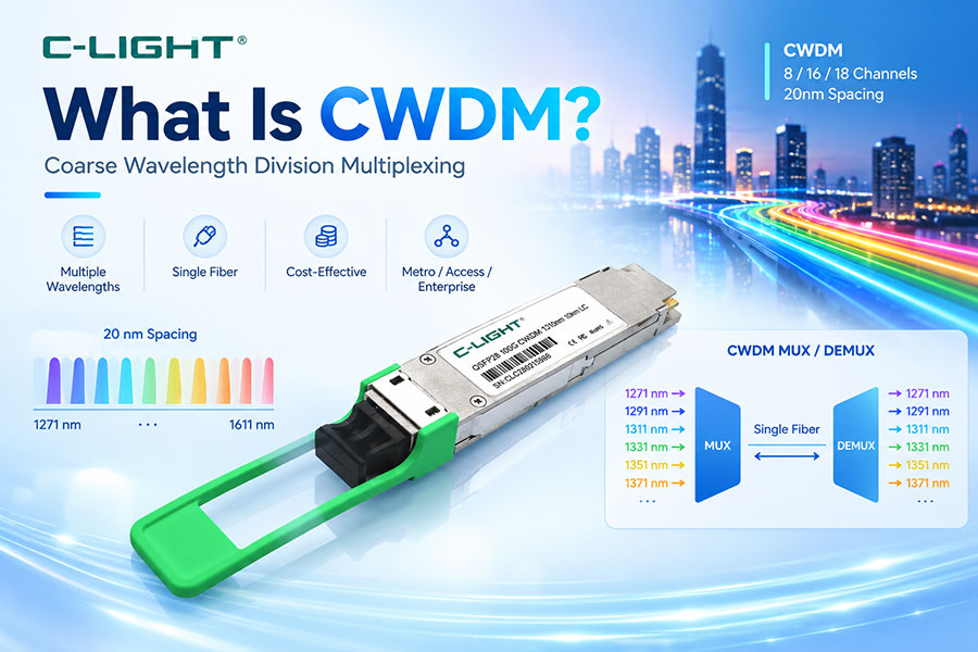
Common data center wavelengths include 850nm for many multimode short-reach applications and 1310nm or 1550nm-class wavelengths for various single-mode applications.
BiDi transceivers require particular attention because the two endpoints normally use complementary transmit and receive wavelengths.
13. Check Optical Reach
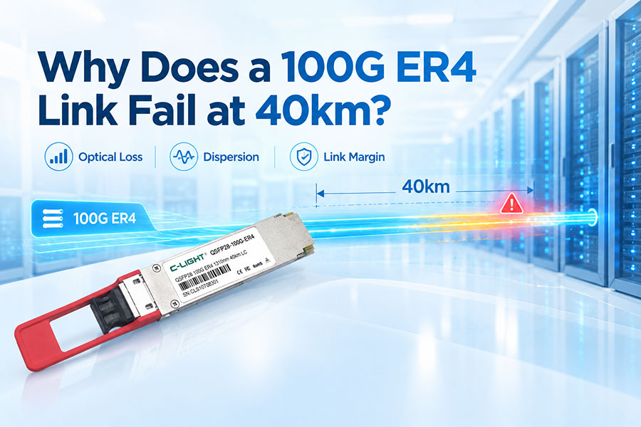
Optical transceivers are designed for specific transmission distances and link budgets. A module intended for a short reach should not automatically be used for a much longer link.
Check the specified reach, fiber attenuation, connector loss, splice loss, and other passive losses against the available optical power budget.
14. Check the Optical Power Budget
The optical power budget determines whether sufficient optical power can reach the receiver after transmission losses.
The basic relationship is:
Optical Margin = Transmitter Output Power − Total Link Loss − Receiver Sensitivity
A link may fail when total loss is too high or when the received optical power falls below the receiver's required sensitivity.
15. Check Tx Optical Power
Use the host device's diagnostic information to check transmitter optical power when available.
Abnormally low Tx power can indicate a transceiver problem, laser issue, temperature-related condition, or other hardware problem.
16. Check Rx Optical Power
Receiver optical power is one of the most useful parameters during troubleshooting.
If the receiver reports very low or no incoming optical power, inspect the fiber, polarity, connectors, remote transmitter, wavelength, and optical path.
17. Check Whether the Rx Power Is Too High
Insufficient optical power is not the only possible problem. A receiver can also be exposed to optical power above its specified operating range.
Excessive input power can cause receiver overload and prevent reliable signal detection. Attenuation may be required in some high-power short links, depending on the transceiver specification.
18. Check the Laser Bias Current
For supported transceivers, laser bias current can provide useful diagnostic information.
An abnormal bias value can indicate changes in laser operating conditions or a potential hardware issue. The expected range depends on the specific optical design and operating temperature.
19. Check the Module Temperature
Optical performance can change with temperature. Laser characteristics, receiver sensitivity, bias current, and electronic components can behave differently outside their normal operating range.
Check the transceiver's temperature monitoring information and compare it with the specified operating range.
20. Check the Host Port Configuration
A correctly installed transceiver may still fail to establish a link if the host interface is administratively disabled or incorrectly configured.
Check whether the interface is enabled and verify the configured speed, breakout mode, FEC, autonegotiation, and other relevant interface parameters.
21. Check the Data Rate
The two endpoints must support compatible data rates.
For example, a 10G SFP+ link, 25G SFP28 link, 100G QSFP28 link, and 400G QSFP-DD link use different electrical and optical interfaces. A mismatch between host configuration and transceiver capability can prevent link establishment.
22. Check FEC Configuration
Forward Error Correction (FEC) is particularly important for high-speed PAM4 interfaces.
Depending on the Ethernet standard and equipment, the correct FEC mode may be required for the link to operate properly. A mismatch in FEC configuration can result in a link that remains down or experiences excessive errors.
23. Check Autonegotiation and Breakout Configuration
High-speed switch ports may support different operating modes, including breakout configurations.
For example, an 800G interface may support different lane or port configurations depending on the host platform. Verify that the selected mode matches the optical transceiver and remote endpoint.
24. Check the Remote Optical Transceiver
Troubleshooting should always consider both ends of the link.
A local transceiver can appear normal while the remote transceiver has low Tx power, incorrect configuration, unsupported coding, excessive temperature, or another fault.
25. Check the Remote Port
The remote host port should also be enabled and configured correctly.
Check its speed, FEC, breakout mode, interface state, transceiver recognition, and diagnostic information.
26. Check Tx and Rx Direction
Optical transceivers contain separate transmit and receive paths. The local transmitter must reach the remote receiver, while the remote transmitter must reach the local receiver.
Incorrect fiber polarity is therefore a simple but important cause of link failure.
27. BiDi Transceiver Pairing
BiDi optical transceivers use different wavelengths for transmitting and receiving over a single fiber.
The two modules must form a compatible wavelength pair. Using two modules with the same wavelength configuration can prevent the receiver from detecting the expected optical signal.
28. Check the Connector Type
Different transceivers use different optical connector configurations, including LC duplex and MPO/MTP.
Verify that the connector type, fiber count, polarity, and mating interface match the transceiver specification.
29. Check MPO/MTP Fiber Polarity
MPO/MTP links can carry multiple parallel optical channels, making polarity and channel mapping especially important.
A polarity or channel mapping problem can cause partial or complete link failure depending on the optical architecture.
30. Check Fiber Attenuation
Fiber attenuation increases the total optical loss of the link. Longer fiber, unsuitable fiber type, poor-quality connectors, excessive bends, and other conditions can increase attenuation.
Measure the link where necessary instead of relying only on the nominal cable length.
31. Check Connector and Splice Loss
Every connector and splice can introduce additional optical loss. A link may fail when accumulated loss approaches or exceeds the available optical budget.
This is particularly important for long-reach links and complex patching environments.
32. Check Excessive Fiber Bending
Sharp bends can increase optical attenuation. High-density data center cabling should follow the specified minimum bend radius of the fiber and cable assembly.
Inspect cable routing when a link shows unexpectedly high loss.
33. Check Signal Integrity on High-Speed Links
For 400G, 800G, and higher-speed interfaces, electrical signal integrity can become an important factor in link establishment.
Host PCB loss, connector characteristics, crosstalk, reflections, package effects, and SerDes performance can affect the electrical signal before it reaches the optical engine.
34. PAM4 Links Require Additional Attention
Many modern high-speed optical interfaces use PAM4 signaling. PAM4 provides four signal levels and carries two bits per symbol, increasing data throughput per lane.
However, PAM4 has smaller eye openings than traditional NRZ signaling and can be more sensitive to noise, loss, crosstalk, reflections, and other impairments.
35. Check BER and FEC Counters
When the physical link appears to establish but does not remain stable, check bit error rate and FEC statistics.
Increasing corrected or uncorrected errors can indicate insufficient link margin, electrical signal-integrity problems, optical degradation, or configuration issues.
36. Check DOM/DDM Diagnostics
Many optical transceivers support Digital Optical Monitoring (DOM) or Digital Diagnostic Monitoring (DDM).
Useful parameters can include:
Module temperature
Supply voltage
Tx optical power
Rx optical power
Laser bias current
These values can help narrow down whether the problem is associated with the local module, optical path, or remote endpoint.
37. Check Alarm and Warning Information
Optical modules and host devices can report alarms or warnings when monitored parameters exceed defined thresholds.
Review the device logs and module diagnostics for indications of temperature, voltage, optical power, laser bias, or hardware faults.
38. Check Firmware and Software
Host firmware and network operating system versions can affect transceiver recognition and port operation.
If a module works on one platform but not another, compare firmware versions, supported transceiver lists, configuration requirements, and platform-specific limitations.
39. Interoperability Can Cause Link Failure
Two optical transceivers may meet the same nominal optical specification but still require interoperability validation at the system level.
This is especially important for high-speed 400G and 800G interfaces, where electrical channel characteristics, FEC behavior, host SerDes, module electronics, and firmware can all affect link performance.
40. Test with a Known-Good Transceiver
Replacing the suspected module temporarily with a known-good compatible transceiver can help isolate the problem.
If the link comes up immediately, the original transceiver should be investigated. If the link remains down, continue checking the host, fiber, remote endpoint, and configuration.
41. Test with a Known-Good Fiber
A known-good fiber patch cable can be used to isolate cabling problems.
This is particularly useful when the original fiber has unknown history, excessive bends, contamination, damaged connectors, or uncertain polarity.
42. Use a Loopback Test
Optical loopback testing can help determine whether a host port and transceiver are functioning correctly.
The exact loopback method depends on the transceiver type and host platform. The test should use a compatible loopback device and follow the equipment manufacturer's specifications.
43. Common Optical Link Failure Causes
| Possible Cause | Typical Check |
|---|---|
| Module not recognized | Check insertion, compatibility, EEPROM, coding |
| Fiber polarity | Verify Tx-to-Rx connection |
| Dirty connector | Inspect and clean connectors |
| Wrong fiber type | Check MMF or SMF requirement |
| Wavelength mismatch | Verify Tx/Rx wavelength compatibility |
| Insufficient Rx power | Check optical loss and remote Tx power |
| Excessive Rx power | Check receiver input range |
| Host configuration | Check speed, FEC, port state, breakout |
| Remote port configuration | Check remote interface settings |
| Temperature | Check module operating temperature |
| Electrical signal integrity | Check channel loss, SerDes, PCB and connectors |
| Interoperability | Test compatible module combinations |
| Hardware failure | Test with known-good components |
44. A Practical Troubleshooting Sequence
A structured troubleshooting process can reduce unnecessary component replacement.
Check whether the host recognizes the transceiver.
Verify the module form factor and compatibility.
Check whether the interface is administratively enabled.
Verify speed, FEC, breakout, and other port settings.
Inspect and clean the optical connectors.
Verify fiber type and polarity.
Check Tx and Rx optical power.
Verify wavelength and optical reach.
Check module temperature and diagnostic alarms.
Check the remote transceiver and remote port.
Test with a known-good fiber.
Test with a known-good compatible transceiver.
Review BER, FEC, and system logs.
Perform deeper optical or electrical testing if necessary.
45. How to Distinguish Optical and Configuration Problems
A useful diagnostic approach is to separate the problem into three areas: host interface, optical path, and remote endpoint.
If the module is not recognized, focus first on the host and module. If the module is recognized but Rx power is absent, investigate the optical path and remote transmitter. If optical power is normal but the link remains down, examine configuration, FEC, electrical signal integrity, interoperability, and remote-port settings.
46. Why High-Speed Links Are More Sensitive
As data rates increase, the available electrical and optical margin can become more difficult to maintain.
At 800G and 1.6T, high-speed lanes, PAM4 signaling, electrical channel loss, thermal conditions, optical performance, and host SerDes characteristics all become important to reliable operation.
47. Optical Transceiver Link Troubleshooting Checklist
Module detected by host
Correct form factor
Compatible transceiver coding
Interface enabled
Correct data rate
Correct FEC mode
Correct breakout configuration
Correct fiber type
Correct polarity
Correct wavelength
Clean optical connectors
Tx optical power within specification
Rx optical power within specification
Module temperature within specification
Remote endpoint operational
BER and FEC counters normal
Host and module interoperability validated
48. Frequently Asked Questions
Q1. Why is my optical transceiver not establishing a link?
Q2. Why is the transceiver detected but the link stays down?
Q3. Can dirty fiber connectors prevent an optical link?
Q4. What should I check when Rx optical power is zero?
Q5. Can excessive optical power cause link failure?
Q6. Can FEC mismatch prevent an 800G link from coming up?
Q7. How can I determine whether the transceiver is faulty?
Q8. Why are 400G and 800G links more difficult to troubleshoot?
49. Summary
An optical transceiver that fails to establish a link can have many possible causes, ranging from a dirty connector or incorrect fiber polarity to host configuration, optical power, FEC, electrical signal integrity, or interoperability issues.
The most effective approach is to troubleshoot the complete link systematically: host → transceiver → fiber → remote transceiver → remote host.
For high-speed 400G, 800G, and 1.6T networks, engineers should pay particular attention to optical power, PAM4 signal integrity, FEC configuration, host SerDes, thermal conditions, and system-level interoperability.
 >
>

 >
>
 >
>
 >
>
 >
>
 >
>
 >
>
 >
>