TEL:+86 132 6656 7067





Large-scale AI training systems distribute GPU resources across multiple server racks. During distributed training, GPUs exchange model parameters, gradients, and intermediate data through high-speed networking fabrics. As the cluster grows, communication between racks becomes a major part of the overall infrastructure design.
Rack-to-rack optical connectivity provides the bandwidth and physical reach required to link leaf switches, spine switches, and network aggregation layers across a data hall. With 400G and 800G deployments expanding and 1.6T interfaces emerging, optical transceivers, fiber assemblies, and structured cabling must be planned as one integrated system.
1. Why Rack-to-Rack Connectivity Matters in AI Training
AI training workloads generate substantial east-west traffic. Instead of communicating only with storage systems or external services, GPU servers exchange data continuously with other nodes participating in the same training job. Communication patterns can involve many servers distributed across different racks.
When a training cluster expands, the network must maintain sufficient bandwidth between rack-level switching systems. Insufficient uplink capacity, oversubscribed switch ports, or poorly planned optical paths can limit communication performance even when individual GPU servers have substantial computing capacity.
Training jobs require coordinated communication between GPU servers. Rack-to-rack links carry traffic between nodes that are not connected to the same local access switch.
Leaf and spine switches aggregate traffic from multiple racks. Their optical uplinks must provide sufficient capacity for the expected cluster size and traffic distribution.
New racks should be added without requiring a complete redesign of the existing fiber plant or switching architecture.
Optical link quality, fiber routing, switch configuration, and congestion management all contribute to predictable communication across the cluster.
2. Rack-to-Rack Connectivity in a Leaf-Spine Architecture
A leaf-spine topology is widely used in scalable data center networks. Each leaf switch connects to server-facing ports and uplinks to multiple spine switches. The spine layer provides paths between leaf switches serving different racks or network zones.
In an AI training cluster, GPU servers connect to the backend fabric through high-speed NICs or host channel adapters. The rack-level leaf switches aggregate these connections, while spine switches provide inter-rack and inter-zone connectivity.
Typical rack-to-rack traffic path:
GPU Server → NIC / HCA → Leaf Switch → Optical Uplink → Spine Switch → Optical Uplink → Destination Leaf Switch → Destination GPU Server
A two-tier leaf-spine fabric can provide a relatively consistent number of network hops between endpoints. As the cluster expands, additional leaf switches and spine capacity can be introduced according to the selected network design.
The physical placement of switches also affects optical cabling. If leaf and spine switches are installed in separate racks, their uplinks become direct rack-to-rack optical connections. In larger facilities, these paths may pass through overhead fiber trays, patch panels, and distribution frames.
3. Choosing 400G, 800G and 1.6T Optical Links
The appropriate optical interface depends on switch capacity, port configuration, network oversubscription targets, link distance, and the expected growth of the AI cluster. Higher data rates can reduce the number of physical ports required for a given aggregate bandwidth, but they also introduce new requirements for host compatibility, optical power, thermal management, and fiber connectivity.
| Optical Link Rate | Typical Network Role | Common Module Families | Planning Considerations |
|---|---|---|---|
| 400G | Leaf-to-spine uplinks and inter-rack aggregation | QSFP-DD, OSFP | Suitable for established high-bandwidth fabrics and phased upgrades |
| 800G | High-capacity leaf-spine connections and larger AI fabrics | OSFP, QSFP-DD800 | Requires careful attention to host interface, lane mapping, thermal limits, and fiber type |
| 1.6T | Next-generation high-density switching and backbone links | OSFP224 and platform-specific interfaces | Requires compatible switch hardware, higher lane rates, and a suitable optical infrastructure |
A migration from 400G to 800G or 1.6T should not be treated as a simple transceiver replacement. The switch ASIC, host electrical interface, module form factor, firmware, thermal design, and fiber plant must all support the intended configuration.
C-LIGHT offers 400G optical transceiver options in OSFP and QSFP-DD form factors for high-speed data center and network switching applications. Available variants should be selected according to the required reach, fiber interface, and host platform.
View 400G OSFP ProductsView 400G QSFP-DD Products
For higher-capacity AI networking, 800G optical modules can support high-bandwidth switch interconnections. C-LIGHT's 800G product families include different optical configurations for short-reach and single-mode applications. The exact module variant must match the required transmission distance and host interface.
View 800G OSFP ProductsView 800G QSFP-DD Products
The 1.6T OSFP-RHS platform addresses next-generation high-density switching environments. Its application depends on the host system's supported OSFP-RHS interface, thermal requirements, and the selected optical configuration.
View 1.6T OSFP-RHS Products4. Selecting Fiber Types for Inter-Rack Optical Links
The distance between racks is one of the primary factors in fiber selection. A connection between adjacent racks may require a different optical configuration from a link crossing several rows or connecting separate network zones.
| Fiber Type | Typical Application | Advantages | Design Considerations |
|---|---|---|---|
| OM3 Multimode | Short-reach data center connections | Established multimode infrastructure | Reach depends on the optical standard and link rate |
| OM4 Multimode | Short-reach, high-speed optical connections | Higher modal bandwidth than OM3 | Verify the transceiver's supported reach and fiber specification |
| OS2 Single-Mode | Inter-rack, inter-row, and longer data center links | Supports a broad range of single-mode optical applications | Requires matching transceiver wavelength, connector, and link budget |
For large AI facilities, OS2 single-mode fiber is often considered for the structured backbone because it supports a wide range of optical reach options and future network upgrades. Multimode fiber can remain suitable for shorter links when the selected transceiver standard supports the required distance.
The fiber category alone does not determine the supported reach. The optical module specification, wavelength, connector configuration, insertion loss, and total link budget must be evaluated together.
5. MPO/MTP Connectivity and High-Density Fiber Distribution
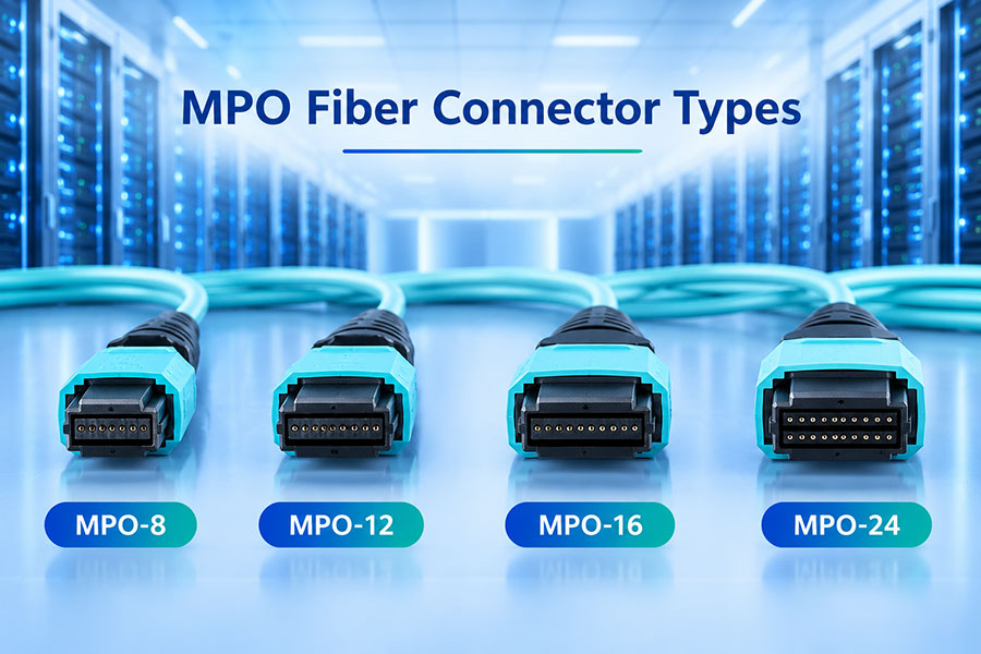
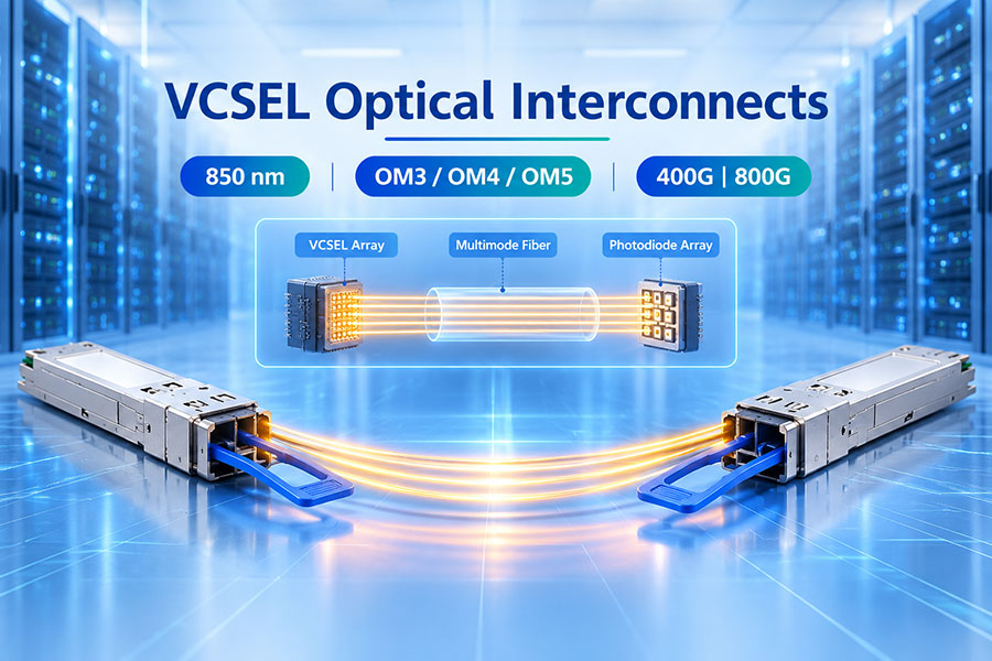
High-speed parallel optical interfaces can use multiple fibers within a single connector. MPO/MTP connectivity helps consolidate many optical channels into compact trunk assemblies, making it useful for dense switching environments where hundreds or thousands of connections may be required.
For rack-to-rack deployments, pre-terminated trunk cables can connect distribution panels in different racks or network zones. Modular cassettes and breakout assemblies can then provide the appropriate connector interfaces for individual transceivers.
Consolidate multiple optical paths into organized cable assemblies and reduce the number of individual cables routed through shared pathways.
Use compatible breakout assemblies to transition between parallel-fiber interfaces and individual optical connections where supported by the transceiver design.
Maintain consistent transmit-to-receive fiber mapping across trunks, cassettes, adapters, and breakout cables.
Inspect and clean connector endfaces before mating. Contamination and poor connections can increase insertion loss and cause link instability.
Fiber count and connector selection must follow the optical module's actual interface specification. MPO-12, MPO-16, and duplex LC are not interchangeable choices, and breakout mapping must be verified before deployment.
6. Optical Transceivers, AOCs and Copper Interconnects
Not every connection inside an AI data center requires the same transmission medium. Rack-to-rack links generally need to account for longer cable routes and structured fiber distribution, while short connections within a rack may use direct-attach copper or active optical cables depending on distance, bandwidth, and equipment layout.
| Interconnect Type | Typical Placement | Main Characteristics | Key Considerations |
|---|---|---|---|
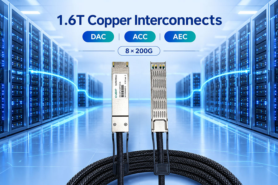
| DAC | Short connections within a rack | Passive copper assembly with low implementation complexity | Reach, cable routing, and host compatibility |
| AEC | Short-reach server and switch connections | Active electrical cable with signal conditioning | Power, latency, supported distance, and platform compatibility |
| AOC | Short-to-medium optical connections | Integrated optical cable assembly | Fixed cable assembly, connector type, and reach |
| Pluggable Optical Transceivers | Rack-to-rack and switch-to-switch links | Replaceable optical modules connected through a structured fiber plant | Optical reach, fiber type, module form factor, and link budget |
For a large training cluster, a mixed interconnect strategy is often more practical than using one cable type throughout the facility. Short copper connections can serve suitable intra-rack links, while optical transceivers and fiber assemblies provide flexibility for rack-to-rack and longer network paths.
C-LIGHT 400G AOC solutions provide integrated optical connectivity for compatible high-speed network equipment. They can be considered for supported short-reach connections where a fixed-length optical cable assembly is appropriate.
View 400G AOC Products7. Managing Bandwidth, Latency and Network Oversubscription
A high-speed optical link does not automatically guarantee high application performance. The effective communication capacity of an AI training fabric also depends on switch architecture, port allocation, routing, congestion control, and the traffic patterns generated by distributed workloads.
Oversubscription occurs when the aggregate bandwidth of downstream connections exceeds the available uplink capacity. Some network designs accept a degree of oversubscription to balance cost and utilization, while bandwidth-intensive training fabrics may require higher uplink capacity to support synchronized communication.
Latency is also influenced by more than the optical medium. Switch processing, network congestion, routing paths, serialization, and endpoint behavior all contribute to end-to-end delay. Fiber selection should therefore be considered alongside the complete network architecture rather than as an isolated latency solution.
Important design priorities:
Calculate the aggregate bandwidth required by each rack.
Define the target oversubscription ratio for leaf-to-spine connections.
Distribute links across available spine switches according to the network design.
Consider failure scenarios and redundant paths.
Validate congestion control and load-balancing behavior under representative training traffic.
8. Power, Thermal Management and Optical Link Reliability
As optical data rates increase, transceiver power and heat dissipation become important considerations in high-density switch racks. The power consumption of an optical module varies by design, data rate, DSP architecture, optical reach, and operating conditions.
A rack populated with many high-speed modules can create a meaningful thermal load around the switch faceplate. Poor airflow, blocked intake paths, or an unsuitable heatsink arrangement may affect module operating conditions and system stability.
Power planning should include the total number of populated optical ports, the specified maximum module power, switch airflow direction, and the platform's thermal limits. Modules must be qualified for the actual host system rather than selected only by data rate and connector type.
For reliable rack-to-rack operation, deployment teams should also monitor optical diagnostics where supported. DOM or DDM readings can help track transmit power, receive power, module temperature, and supply voltage. These readings are useful for identifying changes in link conditions, although they do not replace physical inspection and link testing.
9. Deployment Planning for Large-Scale AI Clusters
A scalable optical infrastructure begins with a clear rack layout and network topology. Fiber routes, switch port assignments, optical module types, and patch-panel configurations should be documented before installation.
Rack topology: Identify GPU racks, leaf switch locations, spine switch racks, and network zones.
Bandwidth planning: Calculate server-facing bandwidth, leaf uplink capacity, and target oversubscription.
Optical selection: Match 400G, 800G, or 1.6T modules to the switch platform and required transmission distance.
Fiber infrastructure: Select OM3, OM4, or OS2 according to the optical standard and link requirements.
Connector mapping: Confirm MPO/MTP fiber count, polarity, key orientation, and breakout configuration.
Physical routing: Maintain bend-radius limits, cable separation, labeling, and accessible service paths.
Link validation: Check insertion loss, receive power, link status, and error counters after installation.
Expansion capacity: Reserve rack space, switch ports, fiber pathways, and patch-panel capacity for future growth.
Testing should cover the complete optical path, not just the transceiver. A qualified module connected through an incorrectly mapped or contaminated fiber assembly can still produce an unstable link. End-to-end validation helps isolate issues across the module, patch cord, trunk cable, panel, and switch port.
10. Building an Upgrade-Ready Optical Fabric
Large AI training clusters evolve as GPU generations, switch capacities, and network architectures advance. A fiber infrastructure designed only around the initial deployment may create additional work when the network moves from 400G to 800G or higher-speed interfaces.
A more flexible approach is to plan backbone fiber capacity, cable pathways, distribution panels, and connector configurations with future expansion in mind. Modular fiber systems can simplify changes to breakout arrangements, while single-mode infrastructure can support multiple generations of compatible optical transceivers.
The upgrade path still depends on the optical interface and switch platform. Higher-speed modules may require different fiber counts, connector types, lane mappings, or thermal capabilities. These requirements should be reviewed during the initial system design rather than after the first deployment.
11. Conclusion
Rack-to-rack optical connectivity is a core part of large-scale AI training infrastructure. It links distributed GPU resources through high-capacity leaf-spine fabrics and provides the physical foundation for scaling network bandwidth across multiple racks and data center zones.
A successful deployment combines the right optical data rate, transceiver form factor, fiber type, connector configuration, and structured cabling design. As 400G and 800G networks expand and 1.6T interfaces enter next-generation platforms, careful planning of bandwidth, thermal capacity, fiber density, and upgrade flexibility becomes increasingly important.
C-LIGHT provides optical transceiver and active optical connectivity solutions for data center and high-performance networking applications. Selecting the right configuration for an AI cluster requires matching the product specification with the target switch, transmission distance, fiber infrastructure, and deployment environment.
Planning Optical Connectivity for an AI Training Cluster?
For product specifications, optical interface selection, and project requirements, contact the C-LIGHT team.
Contact C-LIGHT >

 >
 >
 >
 >
 >
 >
 >