TEL:+86 132 6656 7067





1. What Is a PAM4 Optical Transceiver?
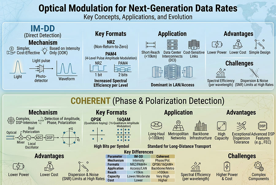
A PAM4 optical transceiver is an optical communication module that uses four-level pulse amplitude modulation to transmit and receive digital data. Unlike traditional NRZ signaling, which uses two signal levels to represent binary information, PAM4 uses four distinct amplitude levels.
Each PAM4 symbol represents one of four possible combinations: 00, 01, 10 or 11. This allows two bits to be transmitted in each symbol interval.
In an optical transceiver, the electrical PAM4 signal is processed by the transmitter circuitry and converted into an optical signal. At the receiving end, a photodetector converts the incoming light into an electrical signal, which is then amplified, equalized and decoded.
PAM4 is widely used in high-speed Ethernet optical applications because it supports higher bit rates per lane while keeping the symbol rate lower than a binary signaling approach operating at the same bit rate.
2. How PAM4 Modulation Works
PAM4 uses four amplitude levels with three decision thresholds at the receiver. Each symbol carries two bits, allowing four possible signal states within one symbol period.
Conceptual representation of the number of distinguishable amplitude states, not a time-domain waveform.
The four levels are typically arranged to provide consistent spacing between adjacent decision regions. The receiver must distinguish among all four states despite noise, distortion, inter-symbol interference and other channel impairments.
For an idealized signaling channel, the relationship between bit rate and symbol rate is:
NRZ bit rate = Symbol rate × 1 bit per symbol
This relationship describes the modulation mapping before accounting for coding and protocol overhead. Actual Ethernet lane rates and symbol rates are defined by the relevant interface specifications.
3. PAM4 vs. NRZ: Key Differences
NRZ (Non-Return-to-Zero) uses two signal levels, while PAM4 uses four. PAM4 can double the number of bits represented by each symbol, but the additional levels reduce the amplitude spacing between adjacent states when the overall signal swing is constrained.
| Comparison | NRZ | PAM4 |
|---|---|---|
| Signal Levels | 2 | 4 |
| Bits per Symbol | 1 bit | 2 bits |
| Data Capacity at Equal Symbol Rate | Baseline | Approximately 2 times |
| Amplitude Decision Regions | 1 decision threshold | 3 decision thresholds |
| Noise Margin | Generally larger level spacing | Smaller adjacent-level spacing |
| Signal Processing | Can use simpler equalization in many applications | Typically requires more advanced equalization and signal processing |
| Error Correction | Depends on the interface standard | FEC is commonly required in high-speed Ethernet applications |
| Typical Applications | Legacy and lower-speed optical links | Modern 50G, 100G and 200G-per-lane systems |
The key advantage of PAM4 is higher data capacity per symbol. Its main challenge is that the receiver must distinguish smaller amplitude differences, making the signal more sensitive to noise, distortion and channel impairments.
4. Why PAM4 Is Used in 400G, 800G and 1.6T Networks
As Ethernet speeds increase, relying only on higher symbol rates becomes increasingly challenging. Faster electrical and optical signaling can increase bandwidth requirements, insertion loss, power consumption and implementation complexity.
PAM4 improves lane efficiency by carrying two bits per symbol. This makes it possible to increase aggregate throughput using multiple high-speed lanes without doubling the symbol rate compared with an equivalent NRZ bit rate.
| Ethernet Generation | Illustrative Lane Configuration | Modulation Approach |
|---|---|---|
| 400G | 4 × 100G or 8 × 50G | PAM4 in common high-speed optical interfaces |
| 800G | 8 × 100G | PAM4 |
| 1.6T | 8 × 200G or other standardized lane configurations | PAM4 in relevant high-speed Ethernet architectures |
These are illustrative lane configurations rather than universal specifications for every optical module. Actual lane counts, electrical interfaces, optical mapping and supported reach depend on the applicable Ethernet standard and transceiver implementation.
For example, 400GBASE-DR4 uses four 100G optical lanes over parallel single-mode fiber, while 400GBASE-SR8 uses eight optical lanes over multimode fiber. Both are examples of PAM4-based high-speed optical applications.
5. Internal Architecture of a PAM4 Optical Transceiver
A PAM4 optical transceiver integrates high-speed electrical processing with optical transmission and reception. Its architecture can vary according to form factor, reach, lane count and whether the design uses a DSP-based or linear signal path.
The major functional components include:
DSP: Performs digital signal processing, including equalization and other functions required by the specific transceiver architecture.
Driver: Converts processed electrical data into signals suitable for driving the optical transmitter.
Laser: Provides the optical carrier used for data transmission.
Optical Modulator: Converts the electrical modulation signal into corresponding optical intensity changes. Some designs use directly modulated lasers instead.
Photodetector: Converts received optical power into an electrical current.
TIA: Converts the photodetector current into a voltage signal for subsequent receiver processing.
Receiver DSP: Recovers the transmitted data from the received electrical waveform.
Not every PAM4 transceiver uses the same internal architecture. The implementation depends on the module's power budget, reach, optical technology and host interface.
6. The Role of DSP in PAM4 Optical Modules
Digital Signal Processing is an important part of many high-speed PAM4 optical transceivers. Because PAM4 has smaller amplitude spacing than NRZ under comparable signal-swing conditions, signal impairments can make it difficult to distinguish the four symbol levels.
DSP helps compensate for channel and transmitter impairments so that the receiver can recover the transmitted data more reliably.
Common signal-processing functions include:
Feed-Forward Equalization (FFE): Compensates for inter-symbol interference by applying weighted signal processing.
Continuous-Time Linear Equalization (CTLE): Adjusts frequency response to compensate for channel loss.
Decision Feedback Equalization (DFE): Uses previous symbol decisions to reduce post-cursor inter-symbol interference.
Clock and Data Recovery (CDR): Recovers timing information and aligns sampling with the incoming signal.
Signal Calibration: Helps manage amplitude, timing and other implementation-dependent variations.
The exact combination of these functions depends on the module and host electrical interface. Some equalization may be implemented in the host ASIC, the transceiver DSP or both.
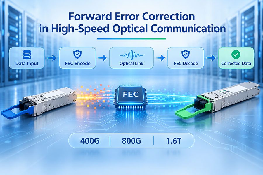
7. Why FEC Is Important in PAM4 Transmission
Forward Error Correction (FEC) adds redundant information to transmitted data so that the receiving system can detect and correct a defined number of errors. It is especially important in high-speed PAM4 Ethernet links because the reduced decision margin can increase sensitivity to signal impairments.
In Ethernet systems, the FEC scheme is specified by the relevant physical-layer standard. Different interfaces may use different coding structures and correction capabilities.
FEC provides several benefits:
Corrects a certain amount of transmission errors before they reach higher network layers.
Improves effective link reliability under specified channel conditions.
Supports higher data rates over practical electrical and optical channels.
Helps maintain acceptable post-FEC bit error performance.
However, FEC introduces coding overhead and processing latency. It also has finite correction capability. If the raw error rate becomes too high, the receiver may exceed the FEC correction limit and the link can experience uncorrectable errors.
8. Key Optical Performance Parameters for PAM4
PAM4 optical transceiver performance cannot be evaluated through average optical power alone. Because the signal contains four amplitude levels, several optical and electrical parameters are important for assessing transmitter quality and receiver performance.
| Parameter | Full Name | Purpose |
|---|---|---|
| OMAouter | Outer Optical Modulation Amplitude | Measures the optical amplitude difference between the outermost PAM4 levels. |
| TDECQ | Transmitter and Dispersion Eye Closure for PAM4 | Evaluates transmitter signal quality while accounting for dispersion and reference equalization. |
| ER | Extinction Ratio | Describes the ratio between specified optical power levels. |
| RIN | Relative Intensity Noise | Measures optical intensity noise relative to the average optical power. |
| Receiver Sensitivity | Minimum required received signal level | Indicates the minimum signal level needed to meet a specified receiver performance target. |
| BER | Bit Error Ratio | Measures the proportion of incorrectly received bits. |
| SECQ | Stressed Eye Closure for PAM4 | Characterizes receiver test stress associated with PAM4 signal quality. |
These parameters are evaluated under defined test conditions. Their limits are not universal values for all PAM4 modules; they depend on the specific Ethernet application and its optical interface specification.
9. Understanding TDECQ and PAM4 Eye Quality
TDECQ is an important transmitter measurement for PAM4 optical interfaces. It estimates the penalty associated with transmitter signal imperfections and optical dispersion relative to a reference receiver equalization process.
Unlike a simple average-power measurement, TDECQ provides information about how well the transmitted PAM4 signal maintains distinguishable levels after relevant channel effects are considered.
Factors that can affect TDECQ include:
Transmitter noise and amplitude distortion.
Nonlinear behavior in the optical transmitter.
Inter-symbol interference.
Optical dispersion within the specified test conditions.
Unequal spacing between PAM4 amplitude levels.
Signal rise and fall characteristics.
A lower TDECQ generally indicates better transmitter signal quality under the applicable measurement conditions. However, TDECQ should be interpreted together with OMAouter, receiver sensitivity and other parameters rather than as an isolated pass/fail indicator.
10. Common PAM4 Optical Transceiver Applications
PAM4 has become a major signaling format in high-speed optical connectivity. Its application is particularly important in environments where aggregate bandwidth and port density are key design requirements.
| Application | Typical Optical Connectivity | Role of PAM4 |
|---|---|---|
| AI Data Centers | 400G and 800G optical links | Supports high-bandwidth connections between switches and AI compute networks. |
| Cloud Computing | 400G/800G Ethernet | Increases data capacity per optical lane. |
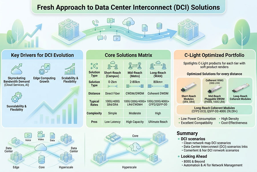
| Data Center Interconnect | High-speed single-mode optical links | Supports higher-capacity connections between network facilities. |
| High-Performance Computing | High-speed optical interconnects | Provides bandwidth for distributed computing systems. |
| Enterprise and Core Networks | High-capacity Ethernet infrastructure | Enables network upgrades toward higher port speeds. |
11. PAM4 in 400G and 800G Optical Transceiver Form Factors
PAM4 is used across multiple optical transceiver form factors, including QSFP-DD and OSFP. The form factor defines the physical module interface, while the optical application defines lane configuration, wavelength, reach, fiber type and other transmission requirements.
Examples of PAM4-based optical applications include:
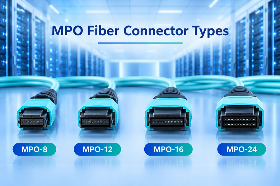
400GBASE-DR4: Four 100G optical lanes over parallel single-mode fiber, typically using an MPO interface.
400GBASE-FR4: Four optical wavelengths multiplexed over duplex single-mode fiber.
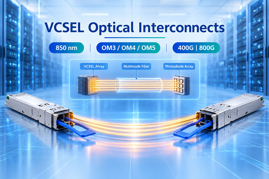
400GBASE-SR8: Eight optical lanes over multimode fiber.
800G DR8: Eight 100G optical lanes over parallel single-mode fiber.
800G 2×FR4: Two groups of four wavelength channels, depending on the specific implementation.
Reach and connector requirements depend on the applicable standard and product specification. PAM4 describes the modulation format, not the fiber type, connector, wavelength or transmission distance.
12. PAM4 Optical Transceiver Testing
Testing a PAM4 optical transceiver requires both electrical and optical measurements. The objective is to verify that the module can transmit and receive the required signal quality under specified operating conditions.
| Test Category | Typical Measurements | Purpose |
|---|---|---|
| Transmitter Testing | OMAouter, TDECQ, extinction ratio and optical waveform | Verify optical signal quality. |
| Receiver Testing | Receiver sensitivity, overload and stressed receiver performance | Evaluate receiver operating margin. |
| Signal Integrity | Eye diagram, jitter and electrical waveform characteristics | Identify signal distortion and timing problems. |
| Error Performance | Pre-FEC and post-FEC BER | Assess transmission errors and correction performance. |
| Environmental Testing | Performance across specified temperature and voltage conditions | Verify operating stability. |
| Compatibility Testing | Host interface, link establishment and interoperability | Confirm operation with supported network equipment. |
For high-speed PAM4 applications, test equipment must support the relevant symbol rate, bandwidth and measurement methodology. Results should be evaluated against the correct application specification rather than generic PAM4 thresholds.
13. Common PAM4 Optical Link Problems
PAM4 links can experience several signal-quality issues when transmitter performance, optical power, fiber conditions or receiver processing are outside the required operating range.
| Potential Issue | Possible Cause | Performance Impact |
|---|---|---|
| High Pre-FEC BER | Insufficient signal quality, noise or excessive channel impairment. | Increased error-correction workload and reduced margin. |
| High TDECQ | Transmitter distortion, noise or inter-symbol interference. | Reduced optical signal quality. |
| Low Received Optical Power | Fiber attenuation, connector loss or transmitter output issues. | Reduced receiver margin. |
| Unstable Link | Host compatibility, signal integrity or environmental problems. | Intermittent link operation or link-down events. |
| Uncorrectable FEC Errors | Raw error performance exceeds the correction capability. | Post-FEC errors and possible link disruption. |
Effective troubleshooting should combine module diagnostics, host-port information, optical power measurements, pre-FEC and post-FEC error statistics, and physical inspection of the fiber connection.
14. PAM4 Optical Transceivers and C-LIGHT High-Speed Connectivity
As network infrastructure moves toward 400G, 800G and 1.6T capacities, PAM4-based optical transmission plays an important role in increasing bandwidth per lane. The appropriate transceiver depends on the required data rate, reach, fiber infrastructure, connector type, host interface and platform compatibility.
C-LIGHT High-Speed Optical Product Portfolio
400G optical connectivity options for data-center switching and high-bandwidth Ethernet networks. Available configurations should be selected according to the required optical application and host platform.
High-speed optical connectivity for compatible switching platforms, supporting different reach and fiber deployment requirements across the product family.
Designed for high-density data-center connectivity and next-generation Ethernet infrastructure.
High-bandwidth optical solutions for AI networks, large-scale switching systems and advanced data-center interconnects.
Next-generation optical connectivity designed for evolving high-capacity switching and data-center network architectures.
Product selection should be based on the exact optical standard, lane configuration, wavelength, fiber type, reach, connector and host electrical interface. A module's form factor or data-rate label alone does not guarantee interoperability.
15. How to Select a PAM4 Optical Transceiver
Choosing a PAM4 optical transceiver requires matching the module's optical and electrical specifications with the network platform and fiber infrastructure.
Data rate: Confirm whether the network requires 400G, 800G or another interface speed.
Form factor: Check QSFP-DD, OSFP or another supported module interface.
Optical standard: Identify the required DR, FR, LR, SR or other application.
Fiber type: Confirm single-mode or multimode fiber requirements.
Transmission distance: Match the module reach to the actual link budget and deployment distance.
Connector: Verify LC, MPO/MTP or other specified optical interfaces.
Host compatibility: Confirm supported switch model, port configuration, firmware and coding requirements.
Signal performance: Review transmitter and receiver specifications, including OMAouter, TDECQ and sensitivity where applicable.
FEC support: Confirm the required FEC mode and host-side configuration.
16. Future Development of PAM4 Optical Technology
PAM4 remains a central signaling technology in high-speed Ethernet optical interconnects. As lane rates continue to increase, transmitter linearity, receiver sensitivity, DSP capability and measurement accuracy become increasingly important.
Future development is expected to focus on:
Higher-speed electrical and optical lanes for next-generation Ethernet.
Improved DSP algorithms and more efficient signal equalization.
Lower-power optical transmitters and receiver circuits.
Better optical packaging and signal integrity at higher bandwidths.
Improved manufacturing consistency and high-speed test coverage.
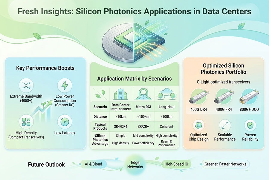
Integration with advanced optical architectures, including CPO and silicon photonics.
PAM4 is not the only modulation format used in optical communications. Coherent optical systems commonly use multi-dimensional modulation formats such as QAM, while short-reach data-center Ethernet continues to use PAM4 in many high-speed lane architectures.
17. Conclusion
PAM4 optical transceivers enable higher data capacity by encoding two bits in each symbol through four distinct amplitude levels. This makes PAM4 an important technology for 400G, 800G and emerging 1.6T Ethernet connectivity.
Its higher signaling efficiency comes with more demanding signal-quality requirements. DSP, FEC, transmitter linearity, receiver sensitivity and accurate optical testing all contribute to reliable PAM4 transmission.
For data-center operators and network equipment designers, selecting the right PAM4 optical transceiver requires a complete evaluation of data rate, optical reach, fiber type, form factor, host compatibility and link performance. As bandwidth requirements continue to grow, PAM4 will remain an important foundation for high-speed optical networking.
Explore High-Speed Optical Connectivity Solutions
C-LIGHT provides optical transceivers and connectivity products for 400G, 800G and next-generation data-center networks. Contact our team for product specifications, compatibility support and project requirements.
Contact C-LIGHT >

 >
 >
 >
 >
 >
 >
 >