TEL:+86 132 6656 7067





High-bandwidth optical networks require transmitters capable of converting high-speed electrical data into stable optical signals with precise timing, controlled modulation and sufficient optical power. As network interfaces advance from 400G to 800G and 1.6T, transmitter design becomes increasingly dependent on the combined performance of laser sources, optical modulators, driver circuits, high-speed electrical interfaces and thermal management. The transmitter is no longer an isolated optical component; it is an integrated subsystem whose electrical and photonic characteristics directly influence link performance, power consumption and deployment reliability.
In modern optical transceivers, transmitter architecture varies according to transmission distance, modulation format, lane count and optical integration technology. Directly modulated lasers, electro-absorption modulated lasers and externally modulated silicon photonics platforms provide different approaches to generating high-speed optical signals. Their suitability depends on bandwidth, linearity, extinction ratio, chirp, optical output power and manufacturing requirements.
1. Optical Transmitter Architecture and Signal Flow
An optical transmitter converts an incoming electrical data stream into an optical signal that can propagate through fiber. Its architecture typically includes an electrical input interface, signal-conditioning circuitry, a laser driver, an optical source, a modulation element and an optical coupling structure.
A simplified transmitter signal path is:
In a directly modulated transmitter, the laser drive current carries the modulation information. In an externally modulated architecture, a continuous-wave laser provides the optical carrier while a separate modulator controls the transmitted signal.
The optical transmitter must maintain several parameters within the target operating range:
Average optical output power: Determines the optical power available at the transmitter output.
Extinction ratio: Describes the optical power contrast between logical signal states.
Optical modulation amplitude (OMA): Represents the optical amplitude difference between signal levels.
Center wavelength: Must remain within the applicable wavelength range.
Rise and fall time: Influences the transmitter's ability to reproduce high-speed signal transitions.
Relative intensity noise (RIN): Describes intensity fluctuations in the optical source.
Output waveform quality: Affects receiver decision performance and the achievable BER.
For PAM4 transmitters, linearity and level separation are especially important because four amplitude levels must be generated and maintained with adequate accuracy.
2. Laser Source Selection: DML, EML and CW Lasers
The laser source is one of the most important elements in transmitter design. Its output power, wavelength stability, linewidth, modulation response and temperature characteristics influence the performance of the complete optical link.
Directly Modulated Laser (DML)
A DML encodes data by varying the laser injection current. The optical output intensity changes in response to the electrical drive signal, eliminating the need for a separate external modulator.
DML technology offers a relatively compact transmitter architecture and can be attractive for cost-sensitive short-reach applications. However, direct modulation can introduce frequency chirp and other dynamic effects that become more difficult to manage as data rates and transmission distances increase.
Electro-Absorption Modulated Laser (EML)
An EML integrates a laser diode with an electro-absorption modulator. The laser generates a continuous optical carrier, while the modulator controls optical transmission through changes in absorption.
EMLs are widely used in high-speed optical communication because they combine compact integration with high-speed modulation capability. Their performance depends on the laser characteristics, modulator bandwidth, bias conditions and driver interface.
Continuous-Wave Laser with External Modulator
An externally modulated transmitter separates optical generation from data modulation. A continuous-wave laser supplies the optical carrier, and an external modulator such as a Mach-Zehnder modulator imposes the electrical data onto the optical signal.
This architecture is important in high-speed silicon photonics and coherent optical systems. It provides flexibility in modulator design and can support advanced modulation formats, although the complete implementation requires additional bias control, drive circuitry and optical integration.
| Transmitter Technology | Modulation Method | Key Characteristics | Typical Application Context |
|---|---|---|---|
| DML | Laser current modulation | Compact architecture and direct optical modulation | Selected short-reach optical links |
| EML | Integrated electro-absorption modulation | High-speed operation and compact integration | High-speed data center and telecom links |
| CW Laser + MZM | External interferometric modulation | Flexible modulation architecture and high-speed operation | Silicon photonics and coherent systems |
3. Optical Modulator Design for PAM4 Transmission
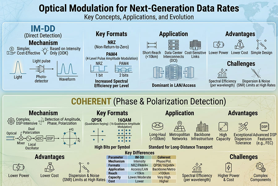
PAM4 is widely used in modern high-speed optical interfaces because it carries two bits per symbol. Compared with NRZ, it doubles the information capacity at the same symbol rate, but it also requires more precise control of the transmitted signal levels.
A PAM4 optical transmitter must generate four distinguishable amplitude states. The driver and modulator need sufficient bandwidth and linearity to maintain appropriate level spacing across the operating frequency range.
Important design parameters include:
Modulator bandwidth: Must support the target symbol rate without excessive signal attenuation.
Electrical linearity: Helps maintain consistent PAM4 level spacing.
Extinction ratio and OMA: Influence the usable optical signal amplitude.
Chirp characteristics: Affect signal propagation and dispersion tolerance.
Electrical termination: Helps reduce reflections and waveform distortion.
Driver output swing: Must match the modulator's voltage requirements.
In practical implementations, transmitter equalization and pre-emphasis may be used to compensate for frequency-dependent losses. The final waveform is determined by the combined response of the host interface, driver, modulator and optical path.
4. Laser Driver and High-Speed Electrical Interface
The laser driver converts electrical data from the host or DSP into a signal suitable for controlling the laser or optical modulator. It must provide the required amplitude, bandwidth, bias current and impedance characteristics without introducing excessive noise or distortion.
At higher data rates, the electrical path between the host SerDes, driver and optical device becomes increasingly sensitive to insertion loss, impedance discontinuities and crosstalk.
Driver Bandwidth and Output Swing
The driver bandwidth determines how accurately the electrical modulation signal can reproduce rapid transitions. Insufficient bandwidth can reduce signal amplitude at high frequencies and increase inter-symbol interference.
Output swing must be matched to the optical device. Excessive drive can cause nonlinear operation or increased power consumption, while insufficient drive can reduce modulation depth and signal quality.
Impedance Matching and Signal Integrity
High-speed electrical interfaces typically require controlled impedance and appropriate termination. Reflections caused by impedance mismatches can distort the waveform and reduce the effective eye opening.
Package parasitics, PCB routing, connectors, wire bonds and interposer structures all contribute to the electrical channel response. These effects become more significant as the interface approaches 200G-per-lane signaling and beyond.
5. TOSA Integration and Optical Coupling
The Transmitter Optical Subassembly (TOSA) integrates the optical source and associated components into a structure that provides a controlled optical output. Depending on the transceiver architecture, the TOSA may include a laser diode, modulator, monitor photodiode, optical isolator and fiber coupling components.
The optical coupling structure is critical because alignment losses directly reduce the power delivered into the output fiber. High-speed transmitter design therefore requires both electrical optimization and precise photonic assembly.
Important TOSA engineering considerations include:
Laser-to-fiber alignment: Maintains efficient optical coupling.
Optical isolation: Reduces unwanted reflections into the laser source where required.
Monitor photodiode integration: Supports optical power monitoring and control.
Mechanical stability: Helps maintain optical alignment under vibration and temperature variation.
Hermetic or environmental protection: Depends on package construction and product requirements.
Thermal path design: Supports stable laser and modulator operating conditions.
In multi-lane optical modules, the transmitter assembly may contain several independent optical channels. Each lane requires consistent coupling, wavelength behavior and output characteristics to support reliable parallel transmission.
6. Optical Output Power, OMA and Extinction Ratio
Optical output power and modulation quality are related but distinct transmitter specifications. Average output power describes the average optical energy delivered by the transmitter, while OMA describes the optical amplitude difference between signal levels.
For NRZ, extinction ratio is commonly used to describe the contrast between the optical high and low states. For PAM4, transmitter evaluation also needs to consider the relative spacing and linearity of the four optical levels.
| Parameter | Engineering Meaning | Design Impact |
|---|---|---|
| Average Optical Power | Mean optical power at the transmitter output | Contributes to the link power budget |
| OMA | Optical amplitude difference between specified signal levels | Influences receiver signal margin |
| Extinction Ratio | Ratio between optical high and low power levels | Describes modulation contrast |
| RIN | Relative optical intensity fluctuations | Contributes to transmitter noise performance |
| Wavelength Accuracy | Deviation from the specified center wavelength | Important for wavelength-dependent systems |
| Transmitter Dispersion Penalty | Signal degradation associated with transmitter characteristics and fiber dispersion | Affects achievable transmission performance |
For multi-level modulation, transmitter specifications should be evaluated under the measurement conditions defined by the relevant interface standard. Average optical power alone is not sufficient to establish whether a PAM4 transmitter meets its signal-quality requirements.
7. Wavelength Control and Temperature Compensation
Laser wavelength changes with temperature and operating current. In wavelength-multiplexed systems, wavelength accuracy is essential because channel spacing and filter passbands constrain the allowable deviation.
A transmitter may use a thermistor, temperature sensor, monitor photodiode and control circuitry to maintain stable operation. Depending on the laser technology and wavelength requirements, a thermoelectric cooler (TEC) may also be used.
Temperature control is especially relevant to DWDM transmitters, where wavelength drift can affect channel alignment and optical filtering. For short-reach parallel optics, the wavelength requirements may be less restrictive, but temperature still influences laser output, modulation characteristics and component reliability.
A practical temperature-control strategy considers:
Laser wavelength variation across the operating temperature range.
Bias current changes and optical output stability.
Modulator bias drift and operating-point control.
Thermal coupling between the laser, DSP and driver.
TEC power consumption and module thermal limits.
8. DSP and Transmitter Equalization
At high data rates, the electrical and optical channels introduce frequency-dependent attenuation, inter-symbol interference and other signal impairments. DSP and transmitter equalization help compensate for these effects.
Depending on the architecture, the transmitter processing chain may include feed-forward equalization, pre-emphasis, pulse shaping and other signal-conditioning functions.
In a PAM4 system, equalization is particularly important because waveform distortion can affect the spacing and timing of all four signal levels. The transmitter and receiver equalization settings must be coordinated to achieve the required end-to-end performance.
In coherent optical systems, transmitter DSP also performs functions such as symbol mapping, pulse shaping and digital compensation associated with the selected coherent modulation format.
9. 400G, 800G and 1.6T Transmitter Architectures
The evolution of optical transmitter design is closely connected to the increasing number of high-speed lanes and the transition toward higher per-lane data rates.
| Network Generation | Common Lane Architecture | Transmitter Design Focus |
|---|---|---|
| 100G | Single-lane or multi-lane architectures depending on interface | NRZ/PAM4 implementation, optical power and signal integrity |
| 400G | Commonly 4×100G-class or 8×50G-class lanes | PAM4 linearity, driver bandwidth and multi-channel integration |
| 800G | Commonly 8×100G-class lanes | High-speed PAM4, optical coupling and thermal management |
| 1.6T | Commonly 8×200G-class lanes | Higher symbol rate, advanced DSP and improved photonic integration |
These are representative architecture patterns rather than universal configurations. Actual lane rates, modulation methods and electrical-to-optical mapping depend on the specific interface standard and module design.
At 400G and 800G, transmitter engineering focuses on maintaining consistent performance across multiple parallel lanes. At 1.6T, higher per-lane bandwidth increases the demands on modulators, drivers, electrical packaging and thermal design.
10. Silicon Photonics and Integrated Optical Transmitters
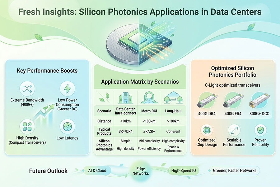
Silicon photonics integrates optical functions such as waveguides, modulators and multiplexers onto a photonic integrated circuit. This approach can reduce component count and support higher levels of optical integration.
A silicon photonics transmitter may combine:
A continuous-wave laser source, either integrated or externally coupled.
Silicon-based Mach-Zehnder or other optical modulators.
Optical waveguides and coupling structures.
Wavelength multiplexers for multi-channel transmission.
Driver electronics and associated control circuits.
The technology is relevant to high-density optical modules and co-packaged optics. Its practical implementation requires careful management of optical coupling loss, modulator efficiency, thermal sensitivity, laser integration and manufacturing tolerances.
Silicon photonics does not automatically eliminate the need for separate laser sources. Many architectures continue to use external continuous-wave lasers, while others investigate different integration approaches.
11. Optical Transmitter Power Consumption and Thermal Management
High-bandwidth transmitters combine laser sources, drivers, DSP and control electronics in a limited mechanical volume. As lane rates and port density increase, thermal design becomes an essential part of transmitter engineering.
The main power contributors may include:
Laser bias and modulation current.
High-speed driver circuits.
DSP and signal-conditioning functions.
TEC and temperature-control circuits where present.
Monitoring and control electronics.
Thermal variation can influence laser wavelength, output power, modulator bias, electrical characteristics and overall component lifetime. A transmitter that performs well under nominal laboratory conditions must also maintain its specified performance across the intended operating temperature range.
High-density 800G and 1.6T modules may require optimized heat spreaders, heatsink structures and airflow management. Liquid-cooling-compatible designs are also relevant in some AI and HPC platforms.
12. Optical Transmitter Testing and Performance Validation
Transmitter validation must cover optical, electrical and environmental performance. Testing should verify that the transmitter meets its applicable interface specification under defined operating conditions.
| Test Item | Measurement Objective | Engineering Value |
|---|---|---|
| Average Optical Power | Measure transmitted optical power | Confirms output power compliance |
| OMA | Measure optical modulation amplitude | Evaluates signal amplitude margin |
| Extinction Ratio | Measure optical high-to-low contrast | Checks modulation quality |
| Eye Diagram | Evaluate waveform opening and distortion | Identifies timing and amplitude impairments |
| Wavelength | Measure center wavelength and stability | Confirms wavelength compliance |
| RIN | Measure relative intensity noise | Evaluates optical source noise |
| BER | Measure transmission error performance | Validates end-to-end signal quality |
| Temperature Cycling | Evaluate performance under temperature variation | Checks environmental stability |
For PAM4 transmitters, additional waveform measurements are required to evaluate level separation, linearity, transition behavior and signal quality. Test conditions must match the relevant standard because results can vary with reference receiver configuration, filtering and measurement methodology.
13. Common Optical Transmitter Failures and Design Risks
Transmitter performance can deteriorate due to optical, electrical, mechanical or thermal factors. A structured failure analysis should examine the complete signal path rather than focusing only on the laser source.
| Observed Issue | Possible Technical Cause | Inspection Direction |
|---|---|---|
| Low optical output power | Laser degradation, bias issue or coupling loss | Check laser drive conditions and optical coupling |
| Unstable optical power | Temperature variation or control-loop instability | Inspect monitor photodiode feedback and thermal control |
| Abnormal extinction ratio | Incorrect bias or modulator operating point | Verify bias settings and modulation waveform |
| Reduced OMA | Insufficient driver swing or modulator degradation | Measure driver output and optical modulation response |
| High BER | Waveform distortion, noise or insufficient optical margin | Check eye quality, receiver sensitivity and link conditions |
| Wavelength drift | Laser temperature or control instability | Measure wavelength over the operating temperature range |
| Intermittent link failure | Electrical signal integrity or thermal instability | Inspect host channel, module temperature and error counters |
A transmitter fault can also originate outside the optical subassembly. Host electrical channel loss, poor grounding, power-supply noise, connector issues and incompatible operating configurations may affect the transmitted signal.
14. Transmitter Design for AI Data Center Networks
AI data centers are increasing the demand for high-density optical connectivity between GPU servers, switches and distributed computing resources. The transmitter must deliver high per-lane bandwidth while maintaining low power consumption and stable operation in dense thermal environments.
Several design priorities are becoming more important:
Higher per-lane bandwidth: 200G-class lanes increase requirements for modulator and driver bandwidth.
Multi-lane consistency: Parallel optical channels need controlled power, wavelength and modulation characteristics.
Thermal efficiency: High port density places greater demands on heatsink and cooling design.
Low signal distortion: PAM4 waveform quality must remain within the required operating limits.
Photonic integration: Silicon photonics and integrated optical assemblies support compact, high-density architectures.
Manufacturing consistency: Alignment, packaging and electrical performance must remain repeatable across production volumes.
The shift toward 1.6T and future optical interfaces will require closer coordination between electrical and photonic design teams. Modulator bandwidth, laser performance, driver linearity and thermal control must be optimized as a single system.
15. C-LIGHT High-Speed Optical Transceiver Solutions
C-LIGHT provides optical transceiver solutions for data center, enterprise, telecom and AI network applications. Its high-speed product portfolio covers multiple form factors, lane configurations and transmission distances.
400G QSFP-DD solutions support high-bandwidth connectivity across multiple optical configurations. Transmitter architecture and optical output requirements vary according to the selected SR, DR, FR or ER interface.
View 400G QSFP-DD Optical TransceiverThe 800G OSFP portfolio includes VR8, SR8, DR8 and 2×FR4 configurations for high-density data center and AI network deployment. Its high-speed transmitter architecture supports multi-lane PAM4 connectivity.
View 800G OSFP Optical TransceiverThe 800G QSFP-DD series supports high-speed optical connectivity in a compact form factor, with configurations designed for different data center transmission distances.
View 800G QSFP-DD Optical TransceiverThe 1.6T OSFP-RHS uses an 8×200G PAM4 architecture with integrated DSP and FEC. Its reduced-height heatsink design addresses the thermal and mechanical requirements of high-density next-generation optical platforms.
View 1.6T OSFP-RHS Optical Transceiver16. Conclusion
Optical transmitter design is a system-level engineering discipline that combines laser technology, optical modulation, driver electronics, signal conditioning, photonic packaging and thermal management. Each component contributes to the final transmitter performance and must be optimized for the intended data rate, transmission distance and operating environment.
DML, EML and external-modulator architectures provide different approaches to generating high-speed optical signals. PAM4 remains central to many 400G and 800G data center interfaces, while the transition to 1.6T increases the demands on 200G-class lanes, electrical bandwidth and photonic integration.
Reliable next-generation optical transmitters require more than higher output power or wider modulation bandwidth. They depend on controlled waveform quality, stable wavelength behavior, efficient optical coupling, accurate electrical drive and comprehensive validation across temperature and operating conditions.
17. Frequently Asked Questions
What is an optical transmitter?
An optical transmitter converts electrical data into an optical signal for transmission through fiber. It typically includes a laser source, modulation circuitry, driver electronics and optical coupling components.
What is the difference between DML and EML?
A DML directly modulates the laser current to encode data. An EML combines a laser source with an electro-absorption modulator, separating optical generation from modulation.
Why is PAM4 widely used in high-speed optical transmitters?
PAM4 carries two bits per symbol, increasing data capacity at a given symbol rate compared with NRZ. It supports higher lane rates but requires more accurate amplitude control and signal processing.
What is the role of a laser driver?
The laser driver supplies the electrical current or voltage required to operate the laser or optical modulator. Its bandwidth, output swing, noise and linearity influence transmitter performance.
What is TOSA in an optical transceiver?
TOSA stands for Transmitter Optical Subassembly. It integrates the transmitter-side optical components, typically including the laser source and optical coupling structure, into a compact assembly.
Why is optical modulation amplitude important?
OMA describes the optical amplitude difference between specified signal levels. It is an important transmitter parameter because it influences the signal available to the receiver.
Does higher optical output power always improve link performance?
No. Link performance also depends on modulation quality, extinction ratio, OMA, noise, fiber attenuation, receiver sensitivity and the applicable optical power limits.
What changes in transmitter design are required for 1.6T?
1.6T architectures commonly use eight 200G-class lanes, increasing the requirements for modulator bandwidth, driver performance, DSP, electrical packaging and thermal management.
How does silicon photonics support high-speed optical transmitters?
Silicon photonics integrates optical waveguides, modulators and multiplexing functions on a photonic integrated circuit. It supports compact, high-density optical architectures, although laser integration and optical coupling remain important design considerations.
Which parameters should be tested during transmitter validation?
Key parameters include average optical power, OMA, extinction ratio, wavelength, RIN, eye quality, BER and temperature stability. PAM4 transmitters also require evaluation of signal-level separation and waveform linearity.
For high-speed optical transceiver specifications, transmitter compatibility or customized optical connectivity requirements, Contact C-LIGHT.
 >

 >
 >
 >
 >
 >
 >
 >