TEL:+86 132 6656 7067




1. Introduction
An optical transceiver converts electrical data into optical signals for transmission and converts received optical signals back into electrical data. Its performance depends on multiple optical, electronic, and control components working together.
2. Main Components of an Optical Transceiver
A typical transceiver includes a laser, modulator, photodetector, driver, TIA, DSP or retimer, controller, optical interface, and power-management circuitry. The exact component set depends on the data rate, reach, modulation, and architecture.
3. Optical Transceiver Signal Path
The transmit path can be simplified as:
Host Electrical Signal → DSP / Driver → Laser or Modulator → Optical Fiber
The receive path is approximately:
Optical Fiber → Photodetector → TIA → DSP / Receiver → Host Electrical Signal
4. Laser
The laser provides the optical carrier used to transmit data. Common laser technologies include VCSEL, EML, DFB, and other laser architectures designed for different wavelengths, speeds, and transmission distances.
5. VCSEL
VCSELs are widely used for short-reach optical links, particularly around 850nm with multimode fiber. They are suitable for many data center connections where transmission distance is relatively short.
6. EML
An EML combines a semiconductor laser with an electro-absorption modulator. It is widely used for high-speed single-mode optical transmission and can provide the performance required for longer-reach applications.
7. DFB Laser
Distributed feedback lasers provide stable single-mode optical output and are commonly used in wavelength-specific optical communication systems. DFB technology can also be combined with external or integrated modulators.
8. Optical Modulator
The modulator changes the optical carrier according to the electrical data. Depending on the architecture, modulation can be provided by an electro-absorption modulator, Mach-Zehnder modulator, or another integrated photonic structure.
9. Photodetector
The photodetector converts incoming optical energy into an electrical current. PIN and avalanche photodiode technologies are commonly used, with the appropriate choice depending on sensitivity, reach, wavelength, and receiver requirements.
10. PIN Photodiode
PIN photodiodes provide a simple and efficient method of detecting optical signals. They are widely used in data communication receivers because of their speed, reliability, and relatively straightforward structure.
11. Avalanche Photodiode
APDs provide internal optical gain and can improve receiver sensitivity in suitable applications. They are more complex than PIN photodiodes and require appropriate bias and control conditions.
12. Transimpedance Amplifier
The TIA converts the small current generated by the photodetector into a usable voltage signal. Its noise, bandwidth, gain, and linearity directly affect receiver performance.
13. Limiting Amplifier
A limiting amplifier can amplify and reshape the electrical signal after the TIA. In some receiver architectures, it helps provide a clean logic-level signal to subsequent processing circuitry.
14. Driver IC
The laser or optical modulator requires an appropriate electrical drive signal. The driver provides the required voltage, current, swing, and high-speed control while maintaining signal integrity.
15. DSP
A digital signal processor can perform functions such as equalization, clock recovery, signal conditioning, and error-related processing. DSPs are especially important in high-speed transceivers, although some linear architectures reduce or remove module-level DSP.
16. CDR
Clock and data recovery circuits extract timing information from the incoming signal and regenerate a clean data stream. CDR functionality can be implemented in the transceiver or handled elsewhere depending on the system architecture.
17. FEC
Forward error correction improves link reliability by allowing the system to detect and correct certain transmission errors. FEC may be implemented in the host system, transceiver, or both depending on the network design.
18. Microcontroller
The microcontroller manages configuration, monitoring, alarms, temperature information, optical diagnostics, and communication with the host system. Modern modules commonly use standardized management interfaces.
19. EEPROM and Module Coding
Module memory stores identification and configuration information such as vendor data, supported capabilities, serial information, and monitoring parameters. Module coding can also affect compatibility with specific switches and routers.
20. Optical Multiplexer and Demultiplexer
WDM transceivers use optical multiplexers to combine multiple wavelengths onto one fiber and demultiplexers to separate them at the receiver. Integrated wavelength components are particularly important in compact multi-channel modules.
21. Optical Coupling
Optical coupling connects the internal optical engine to the external fiber interface. Coupling efficiency directly affects transmitted power, receiver power, and overall link margin.
22. Fiber Interface
The fiber connector provides the physical optical interface. LC is common for duplex single-mode or multimode connections, while MPO/MTP interfaces are widely used for multi-lane high-speed modules.
23. Passive Optical Components
Filters, splitters, wavelength-selective elements, isolators, and other passive components can be used to control optical paths. Their insertion loss and wavelength characteristics contribute to the final optical budget.
24. Thermal Management
High-speed components generate heat, particularly DSPs, drivers, lasers, and other electronic ICs. Heat sinks, thermal interfaces, airflow, and package design are therefore important for maintaining stable optical performance.
25. Power Management
Power-management circuits regulate the different voltage rails required by lasers, DSPs, drivers, TIAs, controllers, and other components. Power efficiency becomes increasingly important as transceiver speeds move from 400G to 800G and 1.6T.
26. Optical Engine
The optical engine groups major optoelectronic functions into a compact subsystem. Depending on the design, it may integrate lasers, modulators, photodetectors, waveguides, drivers, TIAs, and related components.
27. Silicon Photonics
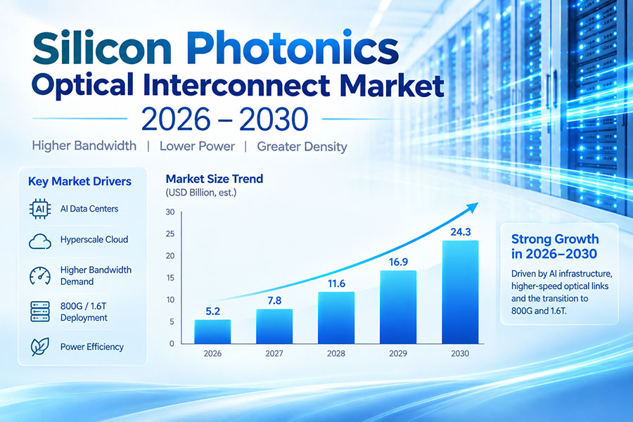
Silicon photonics can integrate waveguides, modulators, wavelength-management structures, and photodetectors on a photonic integrated circuit. It is increasingly relevant to high-density 400G, 800G, and 1.6T optical engines.
28. PAM4 Components
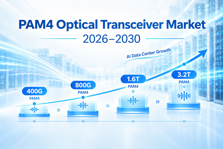
PAM4 uses four signal levels to transmit two bits per symbol. High-speed PAM4 transceivers therefore require carefully designed lasers, modulators, drivers, TIAs, DSPs, and electrical channels to maintain adequate signal quality.
29. Components in 400G, 800G, and 1.6T Modules
| Generation | Typical Architecture | Key Component Considerations |
|---|---|---|
| 400G | Multiple 100G-class lanes | DSP, PAM4, laser, TIA, driver |
| 800G | 8×100G-class or 4×200G-class optical lanes | Higher-speed optics, thermal design, signal integrity |
| 1.6T | 8×200G-class lanes in common architectures | High-speed laser, advanced modulation, DSP, cooling |
30. DSP-Based vs Linear Architectures
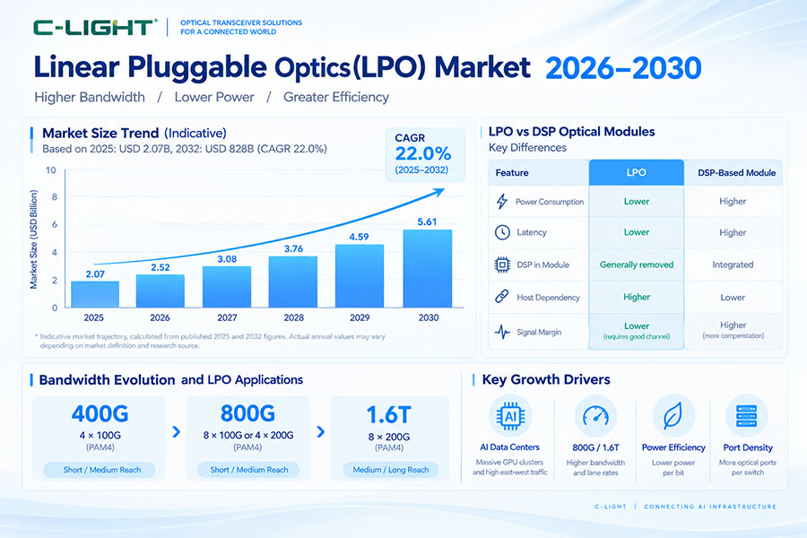
Traditional retimed transceivers commonly include DSP and signal-conditioning functions inside the module. LPO architectures reduce or bypass selected module-level processing and place greater requirements on the host electrical channel, driver, TIA, and system-level signal integrity.
31. Component Selection and Link Reach
No single component determines transmission distance. Reach depends on the complete combination of laser technology, optical power, receiver sensitivity, wavelength, fiber type, modulation, DSP, connector loss, and link budget.
32. Component Quality and Optical Performance
Component quality directly affects transmitter power, receiver sensitivity, extinction ratio, noise, bandwidth, BER, temperature stability, and long-term reliability. Component-level specifications must therefore be evaluated together rather than independently.
33. Component Testing
Important tests can include optical output power, receiver sensitivity, wavelength accuracy, extinction ratio, TDECQ, eye quality, BER, temperature performance, electrical signal integrity, and power consumption.
34. Interoperability
Even when individual components meet their specifications, the complete module must operate correctly with the host switch, router, cable, fiber, and remote transceiver. High-speed PAM4 systems require particular attention to channel loss and interoperability.
35. Why Component Integration Matters
As data rates increase, reducing component count, optical path length, and electrical interconnect complexity becomes increasingly important. Higher integration can support smaller optical engines, higher port density, and more scalable manufacturing.
36. Frequently Asked Questions
Q1. What are the main components of an optical transceiver?
Q2. What does the laser do in an optical transceiver?
Q3. What does a TIA do?
Q4. What is the function of a DSP?
Q5. Are all optical transceivers equipped with DSP?
Q6. What is the difference between a PIN and APD?
Q7. Which components are most important for 800G and 1.6T?
Q8. Does the laser alone determine optical transceiver reach?
37. Summary
An optical transceiver is a combination of optical, electronic, thermal, and control technologies rather than a single component. Lasers and modulators transmit information, while photodetectors and TIAs handle the receive path. Drivers, DSPs, CDRs, controllers, optical interfaces, and power-management circuits complete the system. As 400G, 800G, and 1.6T networks become more demanding, component integration, signal integrity, thermal efficiency, optical coupling, and interoperability become increasingly important to overall transceiver performance.
 >
>

 >
>
 >
>
 >
>
 >
>
 >
>
 >
>
 >
>