TEL:+86 132 6656 7067





1. What Is Optical Transceiver Compliance Testing?
Optical transceiver compliance testing is a set of measurements and verification procedures used to determine whether a module meets the technical requirements defined for its form factor, optical interface and communication application.
A transceiver converts electrical signals from network equipment into optical signals for fiber transmission and converts received optical signals back into electrical data. Both conversion directions must meet their specified performance limits. The module must also communicate correctly with the host device through its electrical and management interfaces.
Compliance testing therefore covers several related areas:
Optical transmitter: Output power, wavelength, modulation quality and signal characteristics.
Optical receiver: Sensitivity, overload behavior and performance under specified signal conditions.
Electrical interface: High-speed lane performance, signal integrity and host-side requirements.
Management interface: Module identification, monitoring information, alarms and control functions.
Mechanical and environmental: Form factor, connector interfaces, operating temperature and applicable durability requirements.
Interoperability: Operation with compatible switches, routers, servers and optical infrastructure.
2. Industry Standards and Specifications
Optical transceiver requirements are defined across several standards organizations and industry groups. The applicable documents depend on the transmission technology, data rate, module form factor and target network.
| Organization or Specification | Main Scope | Relevance to Transceiver Testing |
|---|---|---|
| IEEE 802.3 | Ethernet physical-layer and MAC specifications. | Defines Ethernet PHY requirements, including optical PMD characteristics for supported applications. |
| ITU-T Recommendations | Telecommunication transmission and interface specifications. | Relevant to optical transport, Ethernet physical interfaces and telecom applications. |
| OIF CEI | Common Electrical Interface specifications. | Provides electrical interface requirements used in high-speed chip-to-chip and chip-to-module applications. |
| MSA Specifications | Multi-vendor agreements for module form factors and optical interfaces. | Defines mechanical, electrical, thermal and application-specific requirements for supported module families. |
| IEC 61300 Series | Fiber-optic interconnecting devices and passive component test procedures. | Provides relevant test methods for connector and passive optical interface qualification. |
| CMIS | Common Management Interface Specification. | Defines module management communication, monitoring and control behavior for supported implementations. |
For Ethernet optical modules, IEEE 802.3 defines the relevant physical-layer requirements. Different PHY types have different optical characteristics, reach requirements and test procedures. A 400G DR4 module, for example, should be evaluated against the specification applicable to its particular optical interface rather than a generic 400G checklist.
MSA documents complement standards by defining module-specific implementation details. Form-factor compliance and optical PMD compliance are related but separate: a module may fit a QSFP-DD or OSFP cage while still requiring independent verification of its optical performance.
3. Optical Transmitter Compliance Tests
The transmitter converts electrical input data into an optical signal. Its output must remain within specified limits so that the receiving module can recover the transmitted information under the intended link conditions.
| Test Parameter | What It Evaluates | Why It Matters |
|---|---|---|
| Average Optical Output Power | Average optical power launched by the transmitter. | Ensures the signal is within the specified transmit power range. |
| Optical Modulation Amplitude (OMA) | Difference between optical signal levels under defined conditions. | Characterizes the strength of the modulated optical signal. |
| Extinction Ratio | Relationship between logical high and low optical power levels. | Helps characterize signal contrast and transmitter quality. |
| Center Wavelength | Central wavelength of the transmitted optical signal. | Confirms compatibility with the intended fiber and wavelength plan. |
| Spectral Width | Distribution of optical energy across the signal spectrum. | Important for wavelength and dispersion-related performance. |
| Eye Diagram and TDECQ | Optical waveform quality under the applicable reference conditions. | Evaluates signal distortion and transmitter performance for relevant PAM4 interfaces. |
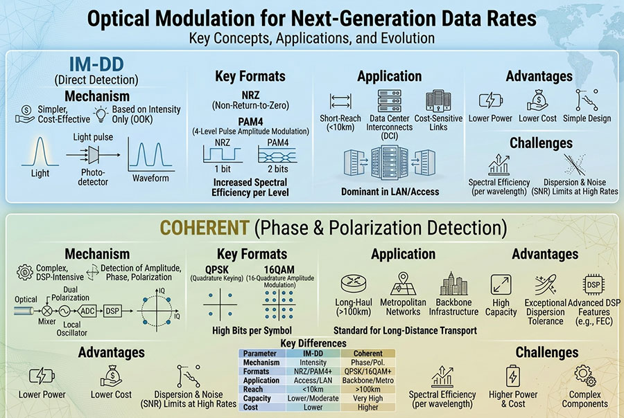
NRZ and PAM4 transmitters require different signal analysis approaches. NRZ uses two signal levels, while PAM4 uses four levels to encode more bits per symbol. PAM4 compliance testing therefore includes measurements that characterize the quality and separation of its optical signal levels.
Depending on the applicable PHY specification, transmitter testing may use an optical sampling oscilloscope, reference receiver, optical spectrum analyzer and calibrated optical power measurement equipment.
4. Optical Receiver Compliance Tests
The receiver converts incoming optical signals into electrical data. Its performance must be verified across the specified input power range and under defined signal conditions.
| Test Parameter | Measurement Objective | Performance Concern |
|---|---|---|
| Receiver Sensitivity | Determines the minimum optical input level at which the receiver meets the specified performance. | Insufficient sensitivity can reduce achievable link reach. |
| Receiver Overload | Determines the upper optical input level the receiver can tolerate under specified conditions. | Excessive input power may cause receiver performance degradation. |
| Bit Error Rate (BER) | Measures the ratio of incorrectly received bits to total transmitted bits. | Indicates data recovery performance under defined test conditions. |
| Stressed Receiver Sensitivity | Evaluates receiver performance with a controlled degraded optical signal. | Provides a more demanding assessment of receiver tolerance. |
| Wavelength Tolerance | Checks receiver behavior across the specified input wavelength range. | Important for WDM and wavelength-dependent applications. |
| Return Loss Tolerance | Evaluates sensitivity to optical reflections where required by the specification. | Helps assess performance in reflective optical paths. |
Receiver sensitivity is not simply the lowest power at which a link happens to remain active. It is measured using a defined optical signal, test pattern, error-rate criterion and measurement setup. For high-speed PAM4 links, the relevant test procedure may also account for FEC and other PHY-specific requirements.
5. Electrical Interface and Signal Integrity Testing
Optical modules also contain high-speed electrical interfaces connecting the module to the host equipment. These electrical lanes carry data between the switch ASIC or network processor and the transceiver. Poor electrical signal quality can affect link performance even when the optical transmitter and receiver meet their individual specifications.
Electrical compliance testing may include:
Eye diagram measurements: Evaluate signal opening and waveform quality at defined electrical test points.
Jitter measurements: Characterize timing variation in the transmitted electrical signal.
Transmitter output characteristics: Verify amplitude, equalization and other specified electrical parameters.
Receiver tolerance: Assess the ability to recover data under defined electrical stress conditions.
Insertion loss and return loss: Characterize relevant high-speed electrical channels and interconnects.
Lane-to-lane consistency: Check that individual electrical lanes operate within their specified limits.
At 400G and 800G, PAM4 signaling and high baud rates make electrical measurement more demanding. Test equipment, fixtures, calibration and reference points must be suitable for the interface under evaluation.
6. BER, FEC and Link Performance Validation
Bit error rate testing is a key part of optical transceiver validation. A bit error rate tester (BERT) generates known data patterns and compares received data with the transmitted sequence to identify errors.
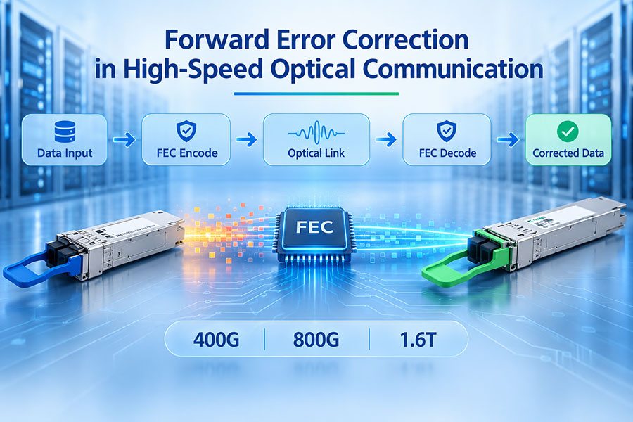
For high-speed Ethernet applications, BER testing should be interpreted alongside the relevant forward error correction requirements. FEC adds error-correction capability to the link, allowing certain transmission errors to be corrected before they affect delivered data.
| Validation Item | Purpose | Typical Use |
|---|---|---|
| Pre-FEC BER | Measures errors before forward error correction. | Characterizes the raw transmission quality of the link. |
| Post-FEC BER | Measures residual errors after FEC processing. | Evaluates delivered data quality after correction. |
| FEC Corrected Codewords | Records the number of codewords requiring correction. | Helps assess the error-correction workload and link margin. |
| FEC Uncorrectable Errors | Identifies errors beyond the correction capability. | Indicates a serious link-quality or interoperability problem. |
| Frame Loss | Measures frames that fail to reach the destination. | Evaluates system-level traffic delivery under test conditions. |
A low post-FEC error rate does not necessarily mean that a link has substantial margin. Pre-FEC BER, corrected codeword counts and FEC behavior can reveal deteriorating signal quality before an obvious service interruption occurs.
7. Management Interface and Module Identification Tests
Modern optical transceivers provide digital management information to the host system. Depending on the module and management specification, this information may include temperature, supply voltage, laser bias current, transmit optical power, receive optical power, alarms and warnings.
Management compliance testing checks whether the module communicates correctly with the host and reports the required information in the expected format.
| Management Test | Verification Objective |
|---|---|
| Module Identification | Verify vendor information, part number, revision and supported interface data. |
| DOM/DDM Monitoring | Check reported temperature, voltage, bias current and optical power values. |
| Alarm and Warning Flags | Verify that threshold conditions are reported according to the specification. |
| Control Functions | Check supported functions such as transmitter disable and low-power mode. |
| Page and Register Access | Verify that supported management data can be accessed correctly. |
| Host Communication | Confirm stable communication between the module and host management interface. |
CMIS and other applicable management specifications define how supported modules expose identification, monitoring and control information. A successful management-interface test is important, but it does not replace optical and electrical performance testing.
8. Mechanical, Thermal and Environmental Testing
Optical transceivers operate inside equipment with limited space, airflow and power budgets. Their mechanical design and thermal behavior must remain suitable for the intended operating environment.
Depending on the product specification and qualification plan, validation may include:
Mechanical dimensions: Confirm module dimensions, cage fit, connector position and latch operation.
Operating temperature: Verify performance across the specified temperature range.
Power consumption: Measure module power under defined operating conditions.
Thermal behavior: Monitor module temperature and performance under representative airflow conditions.
Vibration and shock: Evaluate mechanical robustness when required by the product application.
Connector durability: Assess relevant optical and electrical connection interfaces under applicable qualification procedures.
High-speed modules such as 800G OSFP and 1.6T OSFP-RHS require particular attention to thermal design because power density and airflow conditions can affect operating temperature and long-term stability. Testing should follow the module's specified thermal environment rather than relying on an arbitrary temperature limit.
9. Interoperability Testing Across Network Platforms
Compliance testing and interoperability testing answer different questions. Compliance testing checks whether a device meets defined technical requirements. Interoperability testing checks whether it operates correctly with other equipment in a real system configuration.
Two modules may each pass their individual compliance tests but still encounter compatibility problems when connected to a particular switch or network architecture. Possible causes include host configuration, firmware behavior, management implementation, unsupported operating modes or differences in system-level link settings.
| Test Area | Verification Focus |
|---|---|
| Switch Compatibility | Module recognition, supported speed, port operation and host configuration. |
| Link Establishment | Successful link initialization and stable operation. |
| Traffic Performance | Throughput, packet loss and error counters under defined traffic conditions. |
| FEC Compatibility | Correct FEC mode and expected error-correction behavior. |
| Breakout Configuration | Correct lane mapping and operation in supported breakout modes. |
| Long-Duration Operation | Stable link performance, temperature and error monitoring over time. |
For multi-vendor networks, compatibility should be verified using the actual switch model, port configuration, firmware and module variant intended for deployment. A compatibility result from one host platform should not automatically be generalized to every platform.
10. Compliance Testing for 400G, 800G and 1.6T Modules
Higher data rates increase the importance of lane-level signal quality, modulation performance, thermal control and host-interface validation. Compliance testing must reflect the specific optical architecture rather than treating all modules with the same aggregate data rate as equivalent.
| Module Generation | Common Form Factors | Key Validation Areas |
|---|---|---|
| 400G | QSFP-DD, OSFP, QSFP112 | Optical lane performance, PAM4 quality, BER/FEC, electrical interface and thermal behavior. |
| 800G | OSFP, QSFP-DD | Higher lane density, transmitter and receiver performance, host signal integrity and power consumption. |
| 1.6T | OSFP-related and emerging high-speed module platforms | Next-generation electrical and optical lane performance, advanced thermal design and system interoperability. |
For example, 400G DR4 and 400G FR4 use different optical architectures and should be tested against their respective interface requirements. Similarly, 800G SR8 and 800G DR8 use different fiber types and optical channel arrangements.
For 1.6T platforms, test plans must be based on the applicable published or agreed specification for the specific module implementation. The aggregate data rate alone is not enough to determine the required test limits or procedures.
11. Typical Compliance Testing Workflow
A structured workflow helps ensure that test results are repeatable, traceable and relevant to the module's intended application.
Define the product specification.
Identify the module form factor, data rate, optical interface, wavelength, reach, host electrical interface and applicable standards.Prepare calibrated test equipment.
Select suitable optical and electrical instruments, reference fixtures, test cords and software. Confirm calibration status.Perform visual and mechanical inspection.
Check module dimensions, connector condition, labeling, latch operation and physical workmanship.Measure transmitter performance.
Verify the required optical output parameters using the applicable reference measurement procedures.Measure receiver performance.
Evaluate sensitivity, overload and other required receiver characteristics using controlled optical input signals.Validate electrical and management interfaces.
Check high-speed electrical performance, module identification, monitoring data and supported control functions.Run BER and interoperability tests.
Validate data transmission, FEC behavior and operation with representative host equipment.Complete environmental and thermal validation.
Perform the qualification tests required by the product specification and intended operating conditions.Review and archive test reports.
Record test conditions, equipment details, measured values, pass/fail results and any corrective actions.
12. Common Reasons for Compliance Test Failures
A failed compliance result does not always indicate a defective optical component. The test setup, calibration, reference conditions and host configuration should also be reviewed.
| Observed Problem | Possible Cause | Area to Investigate |
|---|---|---|
| Low Transmit Power | Laser output variation, optical coupling loss or incorrect measurement setup. | Transmitter, optical path and power measurement calibration. |
| Receiver Sensitivity Failure | Receiver degradation, incorrect stressed signal or test configuration. | Receiver front end and optical test conditions. |
| Poor Eye Quality | Signal distortion, electrical noise, jitter or optical transmitter issues. | Electrical input, transmitter and measurement reference. |
| High BER | Insufficient optical margin, signal distortion, lane mapping or FEC mismatch. | Optical channel, electrical interface and system configuration. |
| Incorrect DOM Readings | Calibration, scaling, register mapping or firmware issues. | Monitoring implementation and host management interface. |
| Intermittent Link | Thermal instability, host compatibility or marginal signal quality. | Module temperature, switch configuration and link diagnostics. |
13. C-LIGHT Optical Transceiver Product Solutions
C-LIGHT provides optical transceiver products for data center, enterprise and high-performance computing connectivity. Selecting a module for a compliance or interoperability project requires matching the optical specification, form factor, host platform and intended transmission distance.
400G QSFP-DD Optical Transceivers
400G optical module options for data center switching and high-bandwidth network connections. Selection depends on the required reach, wavelength and fiber architecture.
View 400G QSFP-DD Products800G OSFP Optical Transceivers
High-speed OSFP optical solutions for next-generation data center networks, including parallel and duplex fiber interface options.
View 800G OSFP Products1.6T OSFP-RHS
A high-density optical module platform for emerging 1.6T network architectures. Host compatibility, thermal conditions and interface specifications should be verified for each deployment.
View 1.6T OSFP-RHSFor qualification projects, it is important to define the exact part number and application before testing. Different optical variants within the same form factor can have different wavelengths, reach specifications, fiber interfaces and performance limits.
14. Conclusion
Optical transceiver compliance testing is a comprehensive validation process covering optical transmission, optical reception, electrical signal integrity, management functions, thermal behavior and interoperability. Each test category addresses a different part of module performance, and no single measurement can establish complete compliance.
As 400G, 800G and 1.6T optical technologies develop, test procedures must remain aligned with the specific Ethernet PHY, MSA, electrical interface and management specifications used by the product. Accurate test equipment, controlled reference conditions and traceable reports are essential for reliable results.
For network equipment manufacturers, data center operators and optical module suppliers, a well-defined compliance program helps reduce integration risks, improve product consistency and support dependable multi-vendor connectivity.
Looking for optical transceiver solutions for 400G, 800G or next-generation data center networks? Contact C-LIGHT for product specifications and technical support.
Contact C-LIGHT >

 >
 >
 >
 >
 >
 >
 >