TEL:+86 132 6656 7067





1. What Is Optical Module Insertion Loss?
Insertion loss is the reduction in optical power caused by inserting a component or optical path into a transmission system. It is normally expressed in decibels (dB). A higher insertion loss means that less optical power reaches the receiving end.
In an optical module deployment, the term is commonly used when testing the passive optical path connected to the transceiver. This path may include patch cords, trunk cables, adapters, connector pairs, splices and passive optical devices.
It is important to distinguish passive-path insertion loss from the optical performance specifications of an active transceiver. An optical module performs electrical-to-optical and optical-to-electrical conversion. Its transmitter output power, receiver sensitivity, overload level and bit error rate are evaluated through separate module-level tests. Insertion loss testing evaluates the attenuation introduced by the optical connection between system interfaces.
2. How Insertion Loss Is Calculated
Insertion loss is calculated by comparing the optical power measured before a device or link is inserted with the optical power measured after the optical path is connected. The reference measurement establishes the baseline, while the subsequent measurement shows the power delivered through the path under test.
For example, assume a calibrated reference measurement is -3.0 dBm and the power received through the tested fiber path is -4.2 dBm.
When the reference and measured values are expressed in dBm, their difference is a loss value in dB. This calculation is only meaningful when the source wavelength, launch conditions, connector interfaces and reference method are consistent.
3. Test Equipment and Measurement Setup
A typical insertion loss test uses a calibrated optical light source and optical power meter. Reference-grade test cords and appropriate adapters are required to connect the equipment to the optical path. For more complex installations, an optical loss test set (OLTS) can combine the source and meter functions in a coordinated instrument.
| Equipment | Primary Function | Important Considerations |
|---|---|---|
| Optical Light Source | Provides a stable optical signal at the selected wavelength. | Wavelength and output stability should match the test requirements. |
| Optical Power Meter | Measures optical power at the receiving end. | Check calibration, wavelength setting and measurement range. |
| Reference Test Cords | Provide repeatable connections between test instruments and the link. | Connector type, end-face condition and cord quality affect accuracy. |
| Inspection Microscope | Checks connector end-face condition. | Inspect and clean connectors before making measurements. |
| OLTS | Measures end-to-end optical loss using a coordinated source and meter. | Use a test configuration suitable for the fiber type and link topology. |
The test wavelength should correspond to the optical fiber system being evaluated. Common single-mode testing wavelengths include 1310 nm and 1550 nm, while multimode systems commonly use 850 nm and, where applicable, 1300 nm. For WDM systems, wavelength-specific behavior must also be considered.
4. Common Insertion Loss Testing Methods
The reference method determines which connection losses are included in the measurement. Selecting the correct method is essential because different reference configurations can produce different reported results for the same installed link.
| Method | Configuration | Typical Application |
|---|---|---|
| One-Cord Reference | Uses one reference cord to establish the power baseline. | Testing where the required interfaces and test procedure support this configuration. |
| Two-Cord Reference | Uses launch and receive reference cords. | Measuring a link while including the relevant end connections. |
| Three-Cord Reference | Uses three cords during reference setup and measurement. | Specific cabling configurations where this method is appropriate. |
| OTDR Measurement | Analyzes backscattered light and reflections along the fiber. | Locating events and evaluating loss distribution along a link. |
For installed cabling, the selected method should follow the applicable test standard and the actual connector arrangement. The reference method affects which connections are included or excluded, so results from different methods should not be treated as directly interchangeable without accounting for their measurement configurations.
5. Step-by-Step Insertion Loss Testing Procedure
A repeatable procedure reduces measurement variation and helps separate genuine link loss from errors caused by test cords, connector contamination or inconsistent reference settings.
Identify the optical link.
Confirm the fiber type, connector interfaces, transmission wavelength, link topology and expected optical direction.Inspect the connector end faces.
Inspect and clean the test cords, adapters and link connectors using appropriate fiber-optic inspection and cleaning procedures.Configure the test equipment.
Set the light source and power meter to the required wavelength. Allow the equipment to stabilize according to its operating instructions.Establish the reference power.
Connect the reference cords using the selected test method and record the baseline optical power.Connect the optical path under test.
Insert the link or component into the measurement configuration without changing the required reference arrangement.Measure the received optical power.
Record the power meter reading after the measurement has stabilized.Calculate and evaluate insertion loss.
Subtract the measured power from the reference power and compare the result with the project-specific loss limit.Document the test conditions.
Record wavelength, reference method, test direction, equipment identification, measured loss and acceptance result.
6. Insertion Loss Testing for Different Optical Interfaces
Optical module platforms use different fiber connector and optical interface arrangements. The test configuration must match the actual module and cabling architecture rather than relying on a generic single-fiber test setup.
| Optical Interface | Common Fiber Type | Testing Considerations |
|---|---|---|
| LC Duplex | Single-mode or multimode, depending on module type | Test both optical directions or fibers where required. Verify Tx and Rx paths separately. |
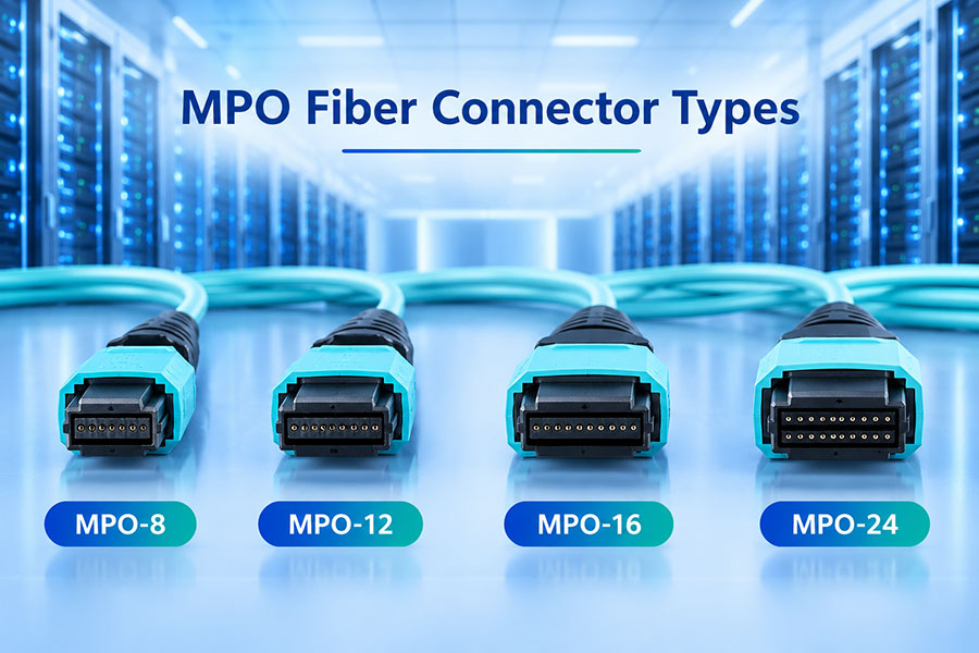
| MPO/MTP | Usually parallel multimode or single-mode fiber arrays | Check polarity, fiber mapping, connector cleanliness and individual channel performance. |
| Single-Fiber BiDi | Single-mode | Use the appropriate wavelength for each transmission direction. |
| WDM Interfaces | Single-mode | Consider wavelength-dependent insertion loss and the characteristics of passive wavelength-selective components. |
For parallel optical interfaces such as 400G SR8 or 800G SR8, a single aggregate power reading may not reveal a problem affecting only one fiber channel. Channel mapping and individual fiber measurements are useful when investigating uneven loss or link instability.
7. Factors That Affect Insertion Loss Results
Measurement accuracy depends on more than the power meter reading. The optical path, test cords, reference configuration and environmental conditions can all influence the result.
| Factor | Effect on Measurement | Recommended Control |
|---|---|---|
| Connector Contamination | Dust or residue can increase attenuation and reflection. | Inspect and clean connector end faces before testing. |
| Connector Damage | Scratches or defects can cause unstable or excessive loss. | Replace damaged connectors or test cords. |
| Fiber Bending | Excessive bending can introduce additional optical attenuation. | Maintain the specified bend radius during testing and installation. |
| Reference Cord Quality | Poor or inconsistent cords can distort the baseline. | Use suitable reference-grade cords and verify their condition. |
| Wavelength Mismatch | Loss may vary with wavelength, particularly in wavelength-selective components. | Measure at the required operating or specified test wavelengths. |
| Instrument Calibration | Incorrect readings can lead to misleading acceptance decisions. | Use calibrated instruments within their specified measurement range. |
| Inconsistent Reference Setup | Different connection arrangements can change the reported loss. | Keep the reference method consistent and document it. |
8. How to Evaluate Insertion Loss and Optical Power Budget
An insertion loss result should be evaluated against the optical link budget, not against an arbitrary universal threshold. Different module types, fiber lengths, connector counts and network architectures have different loss requirements.
The available optical power budget is generally determined by the difference between the transmitter's minimum guaranteed output power and the receiver's specified sensitivity. The actual link must also account for engineering margin and any other applicable system constraints.
For example, if a module has a minimum transmitter output of -2 dBm and a receiver sensitivity of -12 dBm, the nominal power budget is 10 dB. If the passive optical path introduces 4 dB of loss, the remaining nominal margin is 6 dB before other design allowances are considered.
| Evaluation Item | Purpose |
|---|---|
| Transmitter Minimum Output Power | Defines the minimum optical power launched by the transmitting module. |
| Receiver Sensitivity | Defines the minimum received optical power required under specified conditions. |
| Measured Path Insertion Loss | Quantifies attenuation through the installed passive optical path. |
| Engineering Margin | Allows for aging, repairs, additional connections and measurement uncertainty as appropriate to the design. |
A link should be accepted only when its measured loss and other relevant optical parameters satisfy the system design requirements. Receiver overload, optical return loss, dispersion and transceiver-specific operating limits may also need to be considered.
9. Insertion Loss Testing in 400G and 800G Networks
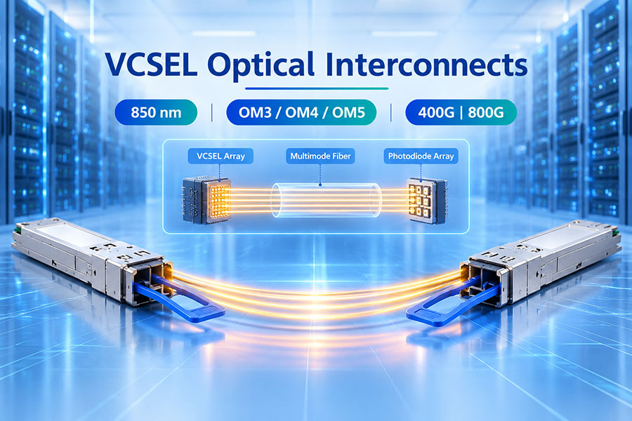
As data center speeds increase from 100G to 400G and 800G, optical connectivity becomes more complex. High-density parallel interfaces, multiple fiber channels and shorter reach budgets make connector quality and channel consistency increasingly important.
For 400G and 800G optical systems, testing should consider the complete optical path between the transmitting and receiving interfaces. Depending on the architecture, this may involve duplex LC connections, MPO/MTP interfaces, breakout assemblies or multiple parallel fiber channels.
| Network Application | Typical Optical Connectivity | Testing Focus |
|---|---|---|
| 400G SR4 | Parallel multimode fiber | Connector condition, polarity and individual fiber-channel loss. |
| 400G DR4 | Parallel single-mode fiber | Single-mode path attenuation and channel mapping. |
| 400G FR4 | Duplex single-mode fiber with wavelength multiplexing | Connector loss and wavelength-dependent optical performance. |
| 800G SR8 | High-density parallel multimode fiber | Per-fiber continuity, polarity and channel-level loss consistency. |
| 800G DR8 | Parallel single-mode fiber | End-to-end attenuation and individual optical path verification. |
| 800G 2×FR4 | Duplex single-mode fiber with multiple optical lanes | Connector performance and wavelength-specific path conditions. |
For parallel optics, engineers should avoid relying only on a single combined measurement if the test objective is to verify every fiber channel. A channel with excessive loss can affect link performance even when the overall optical power appears acceptable.
10. C-LIGHT Optical Transceivers for High-Speed Connectivity
Reliable optical module performance depends on both the transceiver and the quality of the connected fiber infrastructure. C-LIGHT provides optical transceiver solutions for data center, enterprise and high-performance network applications across multiple speed generations.
400G QSFP-DD Optical Transceivers
Designed for high-bandwidth data center connectivity, with optical variants for different fiber types and transmission distances.
View 400G QSFP-DD Products800G OSFP Optical Transceivers
High-speed optical connectivity options for next-generation data center networks, including parallel and duplex fiber architectures.
View 800G OSFP Products800G QSFP-DD Optical Transceivers
Designed for high-density switching and data center interconnect applications requiring 800G optical interfaces.
View 800G QSFP-DD ProductsWhen selecting an optical module, engineers should verify the interface type, wavelength, fiber compatibility, transmission distance, optical power specifications and host equipment compatibility. Insertion loss testing of the connected fiber path should then be performed using a method appropriate to the deployment.
11. Common Testing Problems and Troubleshooting
Possible causes include inconsistent connector mating, contaminated end faces, unstable source output, damaged test cords or changes in the reference configuration. Check the test setup and connector condition before interpreting the variation as a link fault.
A power meter measures optical power. Insertion loss is calculated by comparing the measured power with a properly established reference power. A calibrated source and consistent reference method are therefore required for a meaningful loss measurement.
No. An OTDR locates and characterizes events along a fiber using backscattered light and reflections. An OLTS measures end-to-end insertion loss using a source and power meter. The tools provide complementary information and are not interchangeable for every acceptance test.
Not necessarily. The required wavelengths depend on the fiber type, application and applicable test specification. Single-mode systems may require measurements at 1310 nm and 1550 nm, while multimode systems commonly use 850 nm and may also require 1300 nm testing.
No. Low path loss confirms only one part of the optical link. Module compatibility, transmitter output, receiver sensitivity, optical return loss, signal integrity and bit error rate may also need to be validated.
12. Conclusion
Optical module insertion loss testing is an essential part of validating fiber connectivity in modern optical networks. It provides a measurable indication of attenuation across connectors, patch cords, fiber assemblies and passive optical components, allowing engineers to assess whether the installed path is suitable for the selected transceiver and link budget.
Consistent reference methods, clean connector interfaces, calibrated test equipment and wavelength-appropriate measurements are critical to reliable results. For 400G and 800G deployments, channel-level verification is particularly valuable when using parallel optical interfaces and high-density fiber assemblies.
Combining passive-path insertion loss measurements with module-level optical performance testing helps create a more complete picture of link quality and supports stable network operation.
Looking for optical transceivers for 400G, 800G or other high-speed network applications? Contact C-LIGHT for product information and connectivity support.
Contact C-LIGHT >

 >
 >
 >
 >
 >
 >
 >