TEL:+86 132 6656 7067





High-density AI server racks are changing the physical design of data center networks. A single rack can contain multiple GPU servers, high-speed network adapters, power distribution systems, and cooling infrastructure. Each computing node requires reliable connections to other servers and the switching fabric, creating a dense interconnect environment with demanding bandwidth and thermal requirements.
As AI infrastructure moves from 400G toward 800G and 1.6T connectivity, optical interconnects are becoming increasingly important for connecting GPU systems, rack-level switches, and distributed network layers. The challenge is no longer limited to selecting a high-speed transceiver. Engineers must also coordinate optical port density, fiber routing, connector management, equipment compatibility, and cooling arrangements.
1. Why High-Density AI Racks Need Advanced Optical Connectivity
AI training and inference workloads distribute computing operations across multiple GPUs and servers. These devices exchange large volumes of data through network adapters and switching systems. As the number of accelerators increases, the physical network must provide sufficient capacity without creating excessive cable congestion or thermal constraints.
Traditional data center racks were designed around relatively predictable server and network connections. AI racks introduce a much higher concentration of compute resources and high-speed interfaces. Multiple 400G or 800G links may connect each rack to the wider network, while additional connections support management, storage, and front-end traffic.
Optical interconnects help address several infrastructure requirements:
Higher bandwidth per connection: High-speed optical modules support large data transfers between GPU servers and network switches.
Longer reach: Fiber connections can extend beyond the practical electrical reach of many high-speed copper links.
Lower electromagnetic interference: Optical transmission is not affected by electromagnetic noise in the same way as copper signaling.
Flexible rack placement: Fiber links allow network equipment to be distributed across racks and rows.
Structured connectivity: MPO/MTP trunks, breakout assemblies, and fiber panels help organize large numbers of optical links.
2. Optical Interconnect Architecture Inside an AI Rack
A high-density AI rack can contain GPU servers, network interface cards, top-of-rack switches, and supporting management equipment. The optical architecture depends on the location of each device and the distance between connection points.
GPU Server Layer
GPU servers contain accelerators, CPUs, memory, and high-speed network adapters. External network interfaces connect these systems to the scale-out fabric. Depending on port speed and physical distance, connections may use DAC, AEC, AOC, or pluggable optical transceivers.
Top-of-Rack Switching Layer
ToR switches aggregate network traffic from servers and provide uplinks to the leaf-spine fabric. High-speed optical interfaces can support rack-to-rack and rack-to-network connections where the required reach exceeds the practical range of copper cabling.
Leaf-Spine Network Layer
Leaf and spine switches provide scalable connectivity across multiple racks. Optical transceivers and fiber infrastructure support the high aggregate bandwidth needed for distributed AI workloads.
The physical network should be designed as a complete system. Server ports, switch ports, cable assemblies, optical modules, fiber panels, and patching arrangements must all match the intended topology.
3. Where Optical Links Are Used in High-Density Racks
Not every connection inside or around an AI rack requires the same transmission medium. The choice depends on distance, data rate, port configuration, and cable management requirements.
| Connection Location | Possible Interconnect | Primary Consideration |
|---|---|---|
| GPU server to nearby switch | DAC, AEC, or AOC | Short cable route, port compatibility, and cable density. |
| Server to rack-level optical switch | AOC or pluggable optics | Required reach, optical interface, and cable routing. |
| Rack-to-rack connection | AOC or single-mode optical transceiver | Physical distance, fiber type, and link budget. |
| Leaf-to-spine connection | 400G or 800G optical transceiver | Aggregate bandwidth, port density, and network topology. |
| Next-generation high-density fabric | 800G or 1.6T optical connectivity | Lane architecture, power budget, and thermal design. |
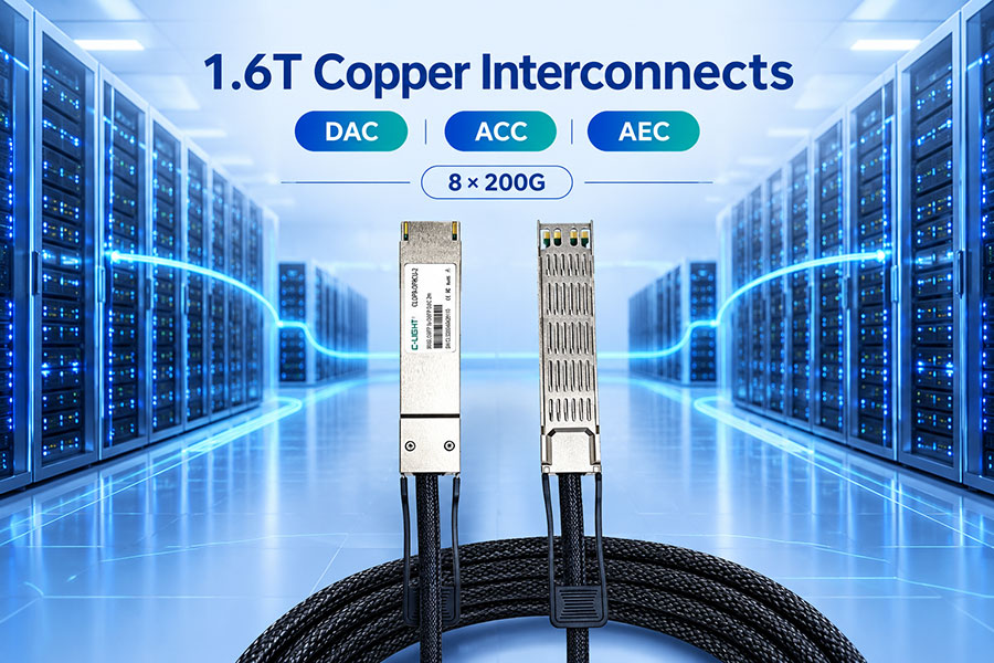
DAC and AEC remain useful for supported short electrical connections. AOC provides an integrated fiber-based assembly, while pluggable optical transceivers offer more flexibility in fiber selection and link reach.
4. 400G, 800G, and 1.6T Optical Connectivity
Increasing port bandwidth allows AI data centers to move more information through each physical connection. This can help support larger clusters and higher-capacity switching fabrics, but each generation introduces different electrical, optical, and thermal requirements.
400G Optical Interconnects
400G connectivity is widely used in high-speed data center switching and AI network infrastructure. Common optical implementations include SR8, DR4, and FR4 configurations, each designed for different fiber types and transmission distances.
In high-density rack environments, 400G modules can provide connections between servers, ToR switches, and network layers where supported by the equipment. Breakout configurations can also connect one high-speed port to multiple lower-speed interfaces when the switch supports the required mapping.
For relevant product options, see C-LIGHT 400G QSFP-DD and 400G OSFP optical transceivers.
800G Optical Interconnects
800G modules increase the bandwidth available from individual network ports. They are particularly relevant to high-capacity AI fabrics where multiple GPU servers generate substantial east-west traffic.
OSFP and QSFP-DD800 are two important form factors for 800G connectivity. The choice depends on host platform support, port design, thermal requirements, and the selected optical architecture.
Representative C-LIGHT options include:
800G OSFP for supported high-speed switching and AI network applications.
800G QSFP-DD for compatible high-density optical platforms.
1.6T Optical Interconnects
1.6T connectivity is an important direction for next-generation AI infrastructure. Representative architectures use eight 200G lanes to deliver an aggregate bandwidth of 1.6Tbps.
Higher lane rates increase the demands on host SerDes, DSPs, optical components, packaging, and cooling. Form factors such as OSFP-RHS are being developed for high-bandwidth applications that require careful thermal integration.
C-LIGHT 1.6T OSFP-RHS optical transceivers are designed for next-generation AI and hyperscale data center applications, with a reduced-height heatsink structure intended for specialized thermal integration.
| Generation | Representative Architecture | Potential Rack-Level Role |
|---|---|---|
| 400G | QSFP-DD / OSFP | Server-facing and switch-to-switch connectivity. |
| 800G | OSFP / QSFP-DD800 | High-capacity rack uplinks and AI fabric switching. |
| 1.6T | OSFP-RHS and emerging high-speed architectures | Next-generation high-density switching and optical fabrics. |
5. Fiber Density and MPO/MTP Connectivity
As the number of high-speed optical links increases, fiber management becomes a major part of rack engineering. Parallel optical interfaces can use multiple transmit and receive fibers within a single connector assembly. Across many servers and switches, the total fiber count can grow quickly.
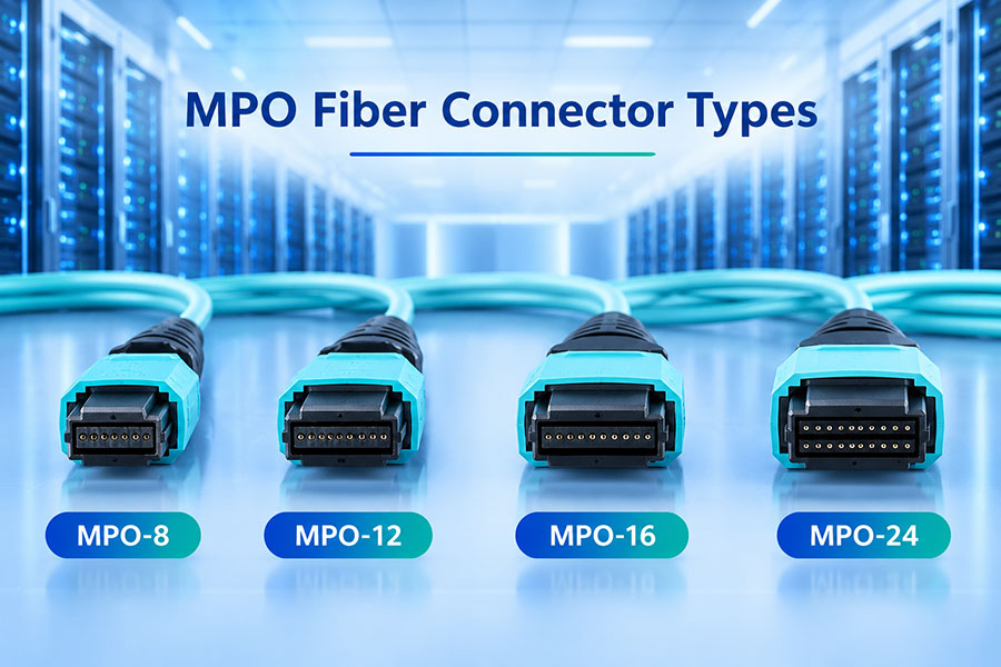
MPO/MTP connectors support multi-fiber connections and are widely used in structured data center cabling. They can connect optical modules to trunk cables, fiber distribution panels, and breakout assemblies.
High-Density Fiber Trunks
Trunk cables consolidate multiple fiber connections into a single assembly. They can reduce the number of individual cable routes and support organized connections between rack equipment and distribution panels.
Breakout Assemblies
Breakout harnesses divide a multi-fiber connection into smaller groups or individual connector interfaces. They are useful when the optical port configuration requires separate transmit and receive paths or connections to multiple lower-speed ports.
Connector Polarity and Mapping
Fiber polarity must match the transmit and receive arrangement at both ends of the link. Incorrect polarity or lane mapping can prevent a connection from establishing or cause optical lanes to be connected incorrectly.
Engineers should verify connector type, fiber count, key orientation, polarity method, and the optical module's lane arrangement before installing large quantities of trunk and breakout cables.
6. Rack Cable Management and Physical Layout
High-density AI racks must accommodate optical cables, electrical cables, power distribution, cooling components, and maintenance access within a limited physical space. Poor cable organization can make equipment replacement difficult and may interfere with airflow or cooling hardware.
A practical cable management plan should address several areas:
Cable length: Select lengths that follow the actual rack route without excessive slack or unnecessary tension.
Routing separation: Organize fiber, copper, and power cables according to the rack's mechanical and safety requirements.
Bend radius: Follow the cable manufacturer's minimum bend-radius specifications to avoid excessive optical loss or physical damage.
Connector access: Keep transceiver ports and fiber connectors accessible for inspection and maintenance.
Labeling: Identify both ends of each cable with consistent rack, device, port, and link information.
Patch panel organization: Use structured fiber distribution where it improves port identification and serviceability.
7. Power Consumption and Thermal Management
Optical modules consume electrical power and generate heat during operation. When a switch contains many active 400G or 800G ports, the combined module power becomes an important part of the equipment's thermal budget.
High-density AI racks add another challenge: optical connectivity must coexist with high-power computing hardware and increasingly sophisticated cooling systems.
Module-Level Power
Power consumption depends on the data rate, optical reach, DSP architecture, laser technology, and receiver design. Two modules with the same nominal bandwidth can have different power requirements if their optical architectures or transmission distances differ.
Switch-Level Thermal Planning
Engineers should evaluate the combined power of all installed modules, not just the power of a single transceiver. Switch airflow, heatsink design, port population, ambient temperature, and neighboring components all affect operating conditions.
Liquid-Cooling Integration
Some high-density AI platforms use liquid cooling to manage heat from processors and other high-power components. Optical module selection must be compatible with the host's cooling arrangement and mechanical design.
Reduced-height heatsink designs such as OSFP-RHS can be relevant in specialized systems using compatible cold-plate arrangements. However, compatibility must be confirmed against the exact module, host cage, and cooling assembly specifications.
| Thermal Factor | Potential Impact | Design Response |
|---|---|---|
| High module power | Increased heat around populated switch ports. | Calculate total port power and verify platform limits. |
| Restricted airflow | Higher operating temperatures. | Maintain the required airflow path and module clearance. |
| Dense cable routing | Reduced service access and potential airflow obstruction. | Use structured routing and suitable cable lengths. |
| Liquid-cooling hardware | Additional mechanical and thermal integration requirements. | Check cold-plate and module compatibility with the host platform. |
8. Choosing DAC, AEC, AOC, and Pluggable Optical Modules
High-density AI racks may use several interconnect technologies within the same network. The best option depends on the connection distance, data rate, port type, cable routing, and system power budget.
| Technology | Transmission Medium | Typical Use | Selection Consideration |
|---|---|---|---|
| DAC | Passive copper | Very short connections within a rack. | Low additional power, but reach is limited. |
| AEC | Active copper | Supported short-reach connections requiring signal conditioning. | Requires power and host compatibility checks. |
| AOC | Integrated optical fiber | Short- and medium-reach connections using a fixed cable assembly. | Check interface configuration, fiber type, and cable length. |
| Pluggable optical transceiver | Optical fiber with separate modules | Rack-to-rack, leaf-spine, and longer optical links. | Provides flexibility in fiber type, reach, and cabling. |
For short connections, DAC or AEC may be appropriate where the equipment supports them. AOC integrates the optical ends and fiber into one cable assembly, which can simplify certain installations. Pluggable optics are useful when the network requires separate transceivers and structured fiber infrastructure.
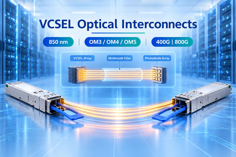
C-LIGHT's 400G AOC product series includes configurations with 850nm multimode transmission, OM3 fiber, and listed cable lengths from 1m to 30m. Actual selection should follow the exact interface and host compatibility requirements.
9. Optical Interconnect Deployment Checklist
Before deploying optical connectivity across a high-density AI rack, engineers should verify the complete connection path and confirm that the selected components meet the equipment requirements.
Map the rack topology: Identify GPU servers, NICs, ToR switches, uplinks, and the intended network paths.
Confirm port speeds: Record the required 400G, 800G, or 1.6T interfaces and supported breakout modes.
Measure cable routes: Determine the actual path length and required cable assembly length.
Select the optical architecture: Choose the appropriate SR, DR, FR, AOC, or other supported solution.
Verify fiber and connectors: Check SMF or MMF, LC or MPO/MTP interfaces, polarity, and lane mapping.
Check equipment compatibility: Confirm form factor, protocol, host coding, firmware, and management requirements.
Review power and cooling: Calculate the module power budget and verify the host thermal design.
Test the complete link: Check link status, optical power, error counters, and network performance.
Document the installation: Maintain cable labels, port maps, product part numbers, and test records.
10. C-LIGHT Optical Connectivity for AI Server Racks
C-LIGHT provides high-speed optical transceivers and cable assemblies for data centers, AI computing infrastructure, cloud networks, and high-performance computing environments. Its product portfolio covers multiple data rates and form factors for different rack-level and network-layer requirements.
400G QSFP-DD Optical Transceivers
The 400G QSFP-DD portfolio includes SR8, DR4, FR4, LR4, and other optical configurations for different transmission distances. These modules can support compatible server and switch connections in high-speed data center networks.
400G OSFP Optical Transceivers
The 400G OSFP series supports high-speed optical connectivity for AI data centers, cloud networks, and HPC systems. Available reach options include SR4, DR4, and FR4 configurations, subject to the specific product model.
400G AOC Active Optical Cables
Integrated optical cable assemblies provide an alternative for supported short-reach connections. The C-LIGHT 400G AOC portfolio includes OSFP and QSFP-related interface combinations, with selected configurations supporting 1m–30m cable lengths.
800G OSFP Optical Transceivers
The 800G OSFP portfolio includes VR8, SR8, DR8, and 2 × FR4 configurations for different data center transmission requirements. These modules are relevant to high-bandwidth switching and AI cluster network expansion.
800G QSFP-DD Optical Transceivers
Designed for compatible 800G platforms, the QSFP-DD800 series provides high-capacity optical connectivity for data center and AI network applications.
1.6T OSFP-RHS Optical Transceivers
The 1.6T OSFP-RHS platform is designed for next-generation high-density optical networks. Its reduced-height heatsink structure is intended for specialized thermal integration environments, including compatible cold-plate cooling systems.
For additional optical modules and connectivity options, visit the C-LIGHT Optical Transceiver Portfolio.
When specifying products for a complete AI rack, customers should provide the host equipment model, port type, required data rate, transmission distance, fiber type, and cooling arrangement. These details help determine the appropriate module and cable configuration.
11. Conclusion
Optical interconnects are a key part of high-density AI server rack infrastructure. As GPU deployments expand and network speeds move from 400G to 800G and 1.6T, the physical connectivity layer must support higher bandwidth while maintaining manageable fiber density, reliable operation, and appropriate thermal performance.
Successful rack design requires more than selecting high-speed optical modules. Engineers must coordinate server and switch interfaces, transmission distances, fiber types, MPO/MTP connectivity, cable routing, power budgets, and cooling arrangements. A combination of DAC, AEC, AOC, and pluggable optical transceivers can address different connection requirements across the rack and wider network fabric.
With careful planning and compatibility validation, optical interconnect infrastructure can provide a scalable foundation for next-generation AI clusters, hyperscale data centers, and high-performance computing networks.
Plan Your AI Server Rack Optical Connectivity
Looking for 400G, 800G, or 1.6T optical transceivers and cable assemblies for high-density AI racks? Contact C-LIGHT for product specifications, interface compatibility, and customized optical connectivity support.
Contact C-LIGHT >

 >
 >
 >
 >
 >
 >
 >