TEL:+86 132 6656 7067





Large-scale AI computing depends on more than GPU processing capacity. Thousands of accelerators must exchange model parameters, gradients, and intermediate data through a network fabric capable of maintaining high throughput and predictable communication performance. As clusters expand across servers and racks, interconnect performance becomes a direct factor in how efficiently computing resources are utilized.
Optical interconnects provide the bandwidth and transmission reach needed for increasingly distributed AI infrastructure. Their role is evolving from conventional switch-to-switch connectivity toward closer integration with compute boards, accelerator packages, and high-speed switching silicon. Bandwidth, latency, and power efficiency must therefore be evaluated together when designing next-generation AI networks.
1. Why Optical Interconnects Are Essential for AI Clusters
AI training workloads generate substantial communication traffic between accelerators. Operations such as AllReduce, AllGather, and ReduceScatter require data to move between multiple GPUs during model training. As the number of accelerators increases, the network must support higher aggregate throughput while managing congestion and communication overhead.
Traditional copper connections remain useful for short electrical paths within servers and racks. However, increasing signaling rates make electrical channel loss, equalization requirements, cable bulk, and reach more difficult to manage. Optical transmission provides an alternative for connections that need greater reach or higher bandwidth density.
Optical interconnects support AI infrastructure in several ways:
Higher aggregate bandwidth: Multiple optical lanes and higher per-lane data rates support high-capacity connections.
Longer transmission reach: Fiber can connect devices across racks and data hall areas without the same electrical channel limitations as copper.
Lower electromagnetic interference: Optical signals are not affected by electromagnetic noise in the same way as electrical signaling.
Flexible network scaling: Optical links support expansion across additional servers, switches, and computing racks.
Potential energy efficiency improvements: Appropriate optical architectures can reduce electrical signal-conditioning requirements over longer connections.
2. Scale-Up and Scale-Out: Different Interconnect Requirements
AI cluster networks are commonly discussed in terms of scale-up and scale-out connectivity. Although both support communication between computing resources, they operate at different architectural levels and have different performance requirements.
Scale-Up Interconnect
Scale-up connectivity links accelerators within a tightly coupled computing system. It emphasizes high bandwidth, low communication overhead, and close integration with compute and memory resources. Depending on the platform, connections may use electrical links, specialized high-speed fabrics, or emerging optical I/O technologies.
Scale-Out Interconnect
Scale-out connectivity links servers, accelerator systems, and network switches across a larger cluster. Ethernet and InfiniBand fabrics are common approaches. Optical transceivers and fiber links are widely used where reach, port density, and bandwidth requirements exceed practical electrical connection limits.
| Network Dimension | Scale-Up | Scale-Out |
|---|---|---|
| Primary purpose | Connect closely coupled accelerators and computing resources. | Connect servers, racks, and distributed accelerator systems. |
| Typical focus | Very high bandwidth density and low communication overhead. | Scalable fabric capacity, reach, and predictable network performance. |
| Connectivity options | Electrical links, optical I/O, and specialized accelerator fabrics. | Ethernet, InfiniBand, optical transceivers, AOCs, and fiber links. |
| Optical integration | Increasing interest in on-board and package-level optical technologies. | Established pluggable optics, with growing adoption of advanced integration. |
Optical connectivity is not automatically the best solution for every scale-up connection. Very short chip-to-chip links may still use electrical interfaces, while optical technology becomes increasingly attractive as reach, bandwidth density, and electrical power constraints grow.
3. Bandwidth: Building High-Capacity AI Network Fabrics
Bandwidth determines how much data can be transferred through a network connection over a given period. In AI clusters, insufficient network capacity can limit communication between accelerators and reduce the efficiency of distributed workloads.
Aggregate Bandwidth and Port Speed
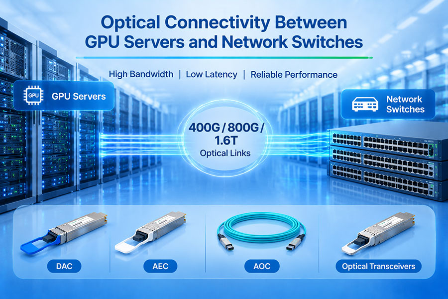
Individual optical links commonly support 400G or 800G Ethernet connectivity, while 1.6T architectures are emerging for next-generation systems. However, the total bandwidth of a cluster is not simply the sum of all installed port speeds. The usable capacity also depends on network topology, uplink ratios, traffic patterns, congestion, and protocol overhead.
| Link Rate | Illustrative Aggregate Capacity | Potential Network Role |
|---|---|---|
| 400G | 400 Gb/s per link | Server connections, leaf-spine links, and AI fabric expansion. |
| 800G | 800 Gb/s per link | Higher-capacity switch ports and large GPU cluster networks. |
| 1.6T | 1.6 Tb/s per link | Next-generation high-density switching and advanced AI connectivity. |
These values represent nominal link rates. Actual application throughput is lower after accounting for protocol overhead, packet headers, encoding, and other network effects.
Lane Speed and Optical Architecture
Higher aggregate data rates can be achieved by increasing the speed of individual lanes, increasing the number of lanes, or combining both approaches. For example, an eight-lane architecture using 100G signaling per lane can provide an aggregate rate of 800G.
The transition toward 200G-per-lane signaling is important for 1.6T optical interfaces. It requires improvements in electrical interfaces, optical components, modulation, signal processing, and packaging.
Network Topology and Oversubscription
Even high-speed optical modules cannot compensate for an inadequately designed network topology. Oversubscription occurs when the aggregate bandwidth of downstream connections exceeds the available capacity of upstream links.
AI network engineers should evaluate:
Server-to-leaf and leaf-to-spine bandwidth ratios.
Number of parallel links between network layers.
Traffic distribution during collective communication operations.
Congestion control and load balancing.
Available bandwidth during equipment failures or maintenance.
4. Latency: Understanding the Optical Link Delay
Latency is the time required for data to travel from a source to a destination. In AI clusters, communication latency affects synchronization, collective operations, and the time required for distributed computing tasks to exchange information.
Optical fiber offers low propagation delay, but total network latency includes more than the time required for light to travel through the cable.
Propagation Latency
Propagation latency is determined by the physical distance and the speed at which light travels through the fiber. The propagation speed in optical fiber is approximately two-thirds of the speed of light in a vacuum.
A useful engineering approximation is about 5 microseconds per kilometer for one-way propagation through fiber. Therefore, a 100-meter fiber link contributes approximately 0.5 microseconds of one-way propagation delay.
Transceiver Processing Latency
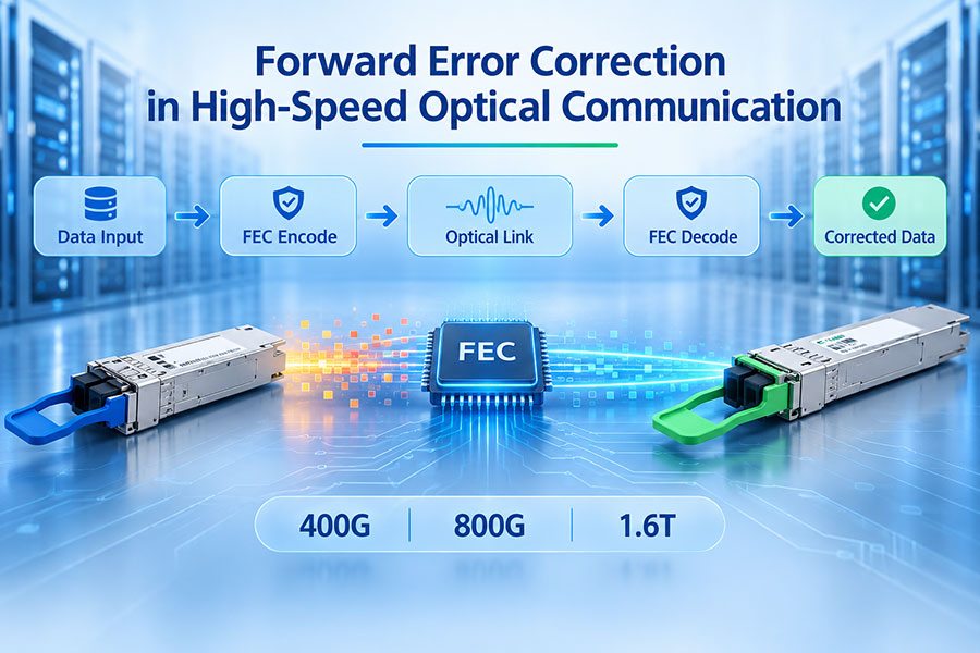
Optical modules may contain DSPs and other electronic circuits that perform equalization, clock recovery, modulation-related processing, and forward error correction. These functions can contribute to link latency.
The actual delay depends on the module architecture, DSP implementation, FEC configuration, and signal-processing method. It should be obtained from the specific product documentation or measured in the target system.
Switching and Queueing Latency
Network switches introduce additional delay through packet processing, buffering, scheduling, and forwarding. When traffic exceeds available output capacity, packets may wait in queues. Congestion can therefore increase end-to-end latency even when the physical optical link is operating correctly.
| Latency Source | Main Influencing Factor | Engineering Consideration |
|---|---|---|
| Fiber propagation | Physical distance and fiber propagation speed. | Keep link routes appropriate for the network architecture. |
| Transceiver processing | DSP, FEC, and signal-processing architecture. | Check module latency specifications. |
| Switch processing | ASIC forwarding and packet-processing behavior. | Evaluate switch architecture and port configuration. |
| Queueing | Congestion, traffic bursts, and buffer occupancy. | Optimize congestion control and load balancing. |
| Protocol overhead | Network stack and transport mechanisms. | Validate end-to-end behavior under realistic workloads. |
5. Power Efficiency: Moving More Data with Less Energy
Power efficiency is becoming a major design consideration as AI clusters scale to thousands of accelerators. Each optical port consumes electrical power, and the combined load of hundreds or thousands of modules can affect rack power budgets and cooling capacity.
Evaluating optical power efficiency requires two complementary measurements: absolute power consumption and energy consumed per transmitted bit.
Module Power Consumption
Optical transceiver power is influenced by:
DSP and signal-conditioning architecture.
Laser technology and optical output requirements.
Driver and receiver electronics.
Transmission distance and optical link budget.
FEC and other signal-processing functions.
Thermal control and power-management circuitry.
Energy per Bit
Energy per bit provides a normalized measure of how much energy is consumed for each transmitted bit. It makes it easier to compare links with different bandwidth capacities, provided that the measurement boundaries are consistent.
For example, an optical link consuming 16W while transmitting at 800G has a simplified module-level energy figure of:
This is an illustrative calculation rather than a specification for a particular optical module. It also does not include switch ASIC power, host SerDes power, cooling energy, or other system-level consumption.
Why System-Level Efficiency Matters
A module with lower power consumption does not always produce the lowest total network energy. A design may require additional components, more optical lanes, different switching configurations, or more cooling capacity.
For meaningful comparisons, engineers should define whether the measurement includes only the optical module, the complete transmitter-to-receiver link, the host electrical interface, or the full network system.
6. Pluggable Optics, LPO, NPO, and CPO
Different optical integration architectures address the challenges of electrical signal loss, bandwidth density, power consumption, and serviceability. They are not interchangeable solutions; each offers a different balance between integration and deployment flexibility.
Conventional Pluggable Optical Transceivers
Pluggable modules such as QSFP-DD and OSFP are installed at the front panel of switches and servers. Their modular design supports replacement, maintenance, and flexible optical reach selection.
They remain important for scale-out AI networks because they provide a mature deployment model and support different optical standards, distances, and fiber configurations.
Linear Pluggable Optics (LPO)
LPO removes the conventional DSP from the optical module and relies more heavily on the host device's electrical interface and signal-processing capability. This can reduce module power consumption and processing latency.
However, the host SerDes, PCB routing, connectors, and optical interface must maintain sufficient signal integrity. LPO therefore requires close coordination between the switch platform and optical module.
Near-Packaged Optics (NPO)
NPO places optical engines closer to the host ASIC than conventional front-panel pluggable modules. Shorter electrical paths can reduce signal loss and the power required for electrical signal conditioning.
Because the optical engines remain separate from the main ASIC package, NPO can provide an intermediate integration approach between pluggable optics and CPO.
Co-Packaged Optics (CPO)
CPO integrates optical engines alongside the switch or compute ASIC within a shared package architecture. The shorter electrical connections can improve bandwidth density and reduce electrical interconnect power.
CPO also introduces new requirements for packaging, optical fiber management, thermal design, laser architecture, and system maintenance. Its advantages must be evaluated across the complete platform rather than by optical engine specifications alone.
| Architecture | Optical Placement | Potential Advantages | Main Considerations |
|---|---|---|---|
| Pluggable Optics | Front-panel module | Modularity, serviceability, and flexible reach options. | Longer electrical path between ASIC and module. |
| LPO | Front-panel module with linear electrical interface | Potentially lower module power and processing latency. | Requires strong host signal integrity and system co-design. |
| NPO | Optical engine near the host ASIC | Shorter electrical paths and higher integration density. | Board-level integration and maintenance considerations. |
| CPO | Optical engine within the ASIC package assembly | Very short electrical paths and high bandwidth density. | Packaging, thermal management, and serviceability complexity. |
7. Silicon Photonics and the Evolution Toward 1.6T
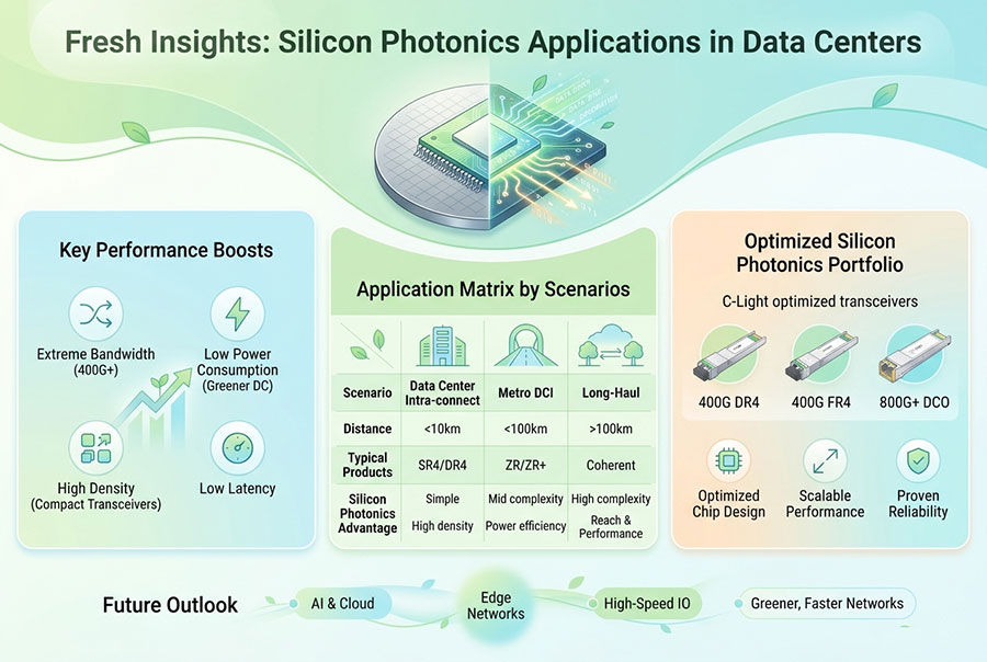
Silicon photonics is an important technology for increasing optical integration density. It uses semiconductor fabrication processes to integrate optical functions such as waveguides, modulators, and photodetectors onto photonic integrated circuits.
For AI networks, silicon photonics can support compact optical engines and higher-bandwidth interfaces. Its role extends from pluggable transceivers to on-board optics and co-packaged optical architectures.
400G Optical Interconnects
400G optical modules are used in high-speed data center networks and AI infrastructure. Available implementations include multimode SR8 and single-mode DR4, FR4, and longer-reach configurations. The appropriate option depends on the link distance, fiber infrastructure, and host interface.
800G Optical Interconnects
800G modules increase the capacity of individual network ports and support higher-density AI fabrics. OSFP and QSFP-DD800 are important form factors, with optical configurations designed for different transmission distances and network applications.
1.6T Optical Interconnects
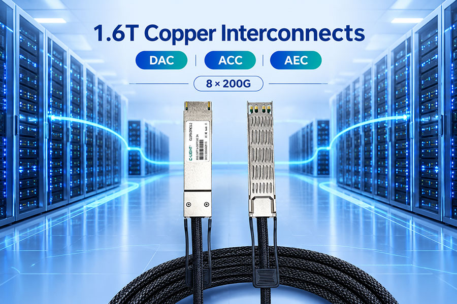
1.6T optical interfaces are designed to provide another increase in port bandwidth. Architectures based on 8 × 200G lanes are an important development direction. Higher lane rates place greater demands on DSPs, electrical interfaces, optical components, packaging, and thermal management.
| Generation | Representative Lane Architecture | Network Direction |
|---|---|---|
| 400G | 8 × 50G or 4 × 100G, depending on implementation. | Established high-speed data center connectivity. |
| 800G | 8 × 100G or other supported lane configurations. | Higher-capacity AI and hyperscale switching. |
| 1.6T | 8 × 200G in representative architectures. | Next-generation high-density optical networking. |
8. Matching Optical Interconnect Technology to Network Requirements
Not every AI cluster connection requires the same optical technology. The selection should follow the actual physical distance, data rate, host interface, fiber infrastructure, and operating environment.
| Connection Scenario | Possible Interconnect Option | Key Selection Factors |
|---|---|---|
| Very short in-rack connection | DAC or AEC | Reach, port speed, cable routing, and host support. |
| Short optical connection | AOC or multimode optical transceiver | Fiber type, connector, cable length, and compatibility. |
| Rack-to-rack connection | 400G or 800G single-mode optics | Transmission distance, link budget, and fiber plant. |
| High-capacity switch uplink | 800G or 1.6T optical interfaces | Port density, aggregate bandwidth, and thermal budget. |
| Future integrated compute fabric | NPO, CPO, or optical I/O | Packaging, serviceability, power efficiency, and system design. |
For conventional scale-out networks, pluggable transceivers provide flexibility across different distances. For very short connections, copper or active copper assemblies may remain appropriate. For future high-density scale-up architectures, deeper optical integration may become increasingly relevant.
9. Engineering Considerations for Reliable AI Optical Networks
High bandwidth alone does not guarantee reliable cluster communication. Optical network design must account for link performance, equipment compatibility, physical installation, and system monitoring.
Define the network architecture: Identify scale-up and scale-out requirements, switch layers, port speeds, and traffic patterns.
Calculate bandwidth demand: Evaluate aggregate link capacity, oversubscription, and expected communication workloads.
Determine transmission distance: Select multimode or single-mode optical solutions according to the actual link route.
Verify interface compatibility: Check form factor, lane configuration, communication protocol, management interface, and host support.
Evaluate power and cooling: Confirm module power, host power budget, airflow requirements, and thermal limits.
Validate latency and link performance: Measure link errors, packet latency, congestion behavior, and application-level performance.
Establish monitoring procedures: Use available DOM/DDM information and network diagnostics to track temperature, optical power, voltage, and link status.
10. C-LIGHT Optical Interconnect Solutions for AI Clusters
C-LIGHT provides optical transceivers and high-speed connectivity products for data centers, AI computing networks, cloud infrastructure, and high-performance computing applications. Its product portfolio covers multiple data rates and form factors to support different network architectures.
400G QSFP-DD Optical Transceivers
The 400G QSFP-DD portfolio includes optical configurations for short-reach data center links, single-mode connections, and selected longer-distance applications. It can be considered for high-speed switch connections and AI network infrastructure where the host platform supports the required interface.
400G OSFP Optical Transceivers
The 400G OSFP series supports high-speed optical connectivity for AI data centers, cloud networks, and HPC systems. Available optical configurations include SR4, DR4, and FR4 options for different link requirements.
800G QSFP-DD Optical Transceivers
The 800G QSFP-DD series supports high-capacity connections for AI-driven networks, hyperscale data centers, and high-speed Ethernet infrastructure. Available configurations include different reach options for supported system platforms.
800G OSFP Optical Transceivers
The 800G OSFP portfolio includes VR8, SR8, DR8, and 2 × FR4 configurations. These modules are designed for high-bandwidth data center switching, AI clusters, and HPC networks.
1.6T OSFP-RHS Optical Transceivers
The 1.6T OSFP-RHS platform supports next-generation optical connectivity for AI clusters and hyperscale data centers. Its reduced-height heatsink design is intended for demanding thermal integration environments, including compatible cold-plate cooling systems.
For additional optical interfaces and transmission options, visit the C-LIGHT Optical Transceiver Portfolio.
Product selection should be based on the required data rate, transmission distance, fiber type, connector, host compatibility, and power and thermal specifications of the exact part number.
11. Conclusion
Optical interconnects are a fundamental part of scalable AI cluster infrastructure. They enable high-capacity communication between servers, switches, and distributed accelerator systems while providing transmission reach and deployment flexibility that are increasingly difficult to achieve with electrical links alone.
Bandwidth determines how much data the network can carry, latency affects how quickly computing resources exchange information, and power efficiency determines the energy required to move that data. These factors must be considered together rather than optimized independently.
As networks advance from 400G and 800G toward 1.6T, optical technologies will continue to evolve through higher lane rates, silicon photonics, LPO, NPO, CPO, and deeper optical integration. The most effective AI interconnect architecture will combine the appropriate technology at each network layer to balance performance, reliability, power consumption, and long-term scalability.
Build High-Performance AI Optical Networks with C-LIGHT
Looking for 400G, 800G, or 1.6T optical transceivers for AI clusters, GPU networks, and high-density data centers? Contact C-LIGHT for product specifications, compatibility support, and optical connectivity solutions.
Contact C-LIGHT >

 >
 >
 >
 >
 >
 >
 >