TEL:+86 132 6656 7067




1. Introduction
AI data centers are scaling rapidly in GPU count, switching capacity, and east-west traffic. As network speeds move through 400G and 800G toward 1.6T, optical connectivity is becoming an important factor in overall system performance. The bottleneck is not simply the optical transceiver itself; it can occur across the electrical channel, optical engine, fiber infrastructure, thermal system, and network architecture.
2. What Is an Optical Bottleneck?
An optical bottleneck occurs when the optical path cannot provide the bandwidth, signal quality, reach, power efficiency, or reliability required by the network. A link may be operational while still limiting throughput because of errors, congestion, insufficient margin, or inefficient optical architecture.
3. Why AI Networks Are Different
Traditional data center traffic can be relatively distributed, while AI workloads often generate highly synchronized communication between large groups of GPUs. Operations such as all-reduce, all-to-all communication, gradient exchange, and parameter synchronization can create intense east-west traffic.
4. The Main Optical Bottlenecks
| Area | Typical Bottleneck |
|---|---|
| Bandwidth | Insufficient optical capacity per port |
| Electrical Interface | Channel loss and signal-integrity limits |
| Power | High DSP and optical-engine consumption |
| Thermal | High heat density around switch ports |
| Reach | Mismatch between module and physical link |
| Fiber | Loss, polarity, density, and cabling constraints |
| Reliability | High sensitivity to link and component failures |
| Interoperability | Host, module, cable, and software mismatches |
5. Bandwidth per Port
Higher bandwidth per optical port helps reduce the number of physical links required for a given aggregate capacity. However, increasing port bandwidth also increases the demands on SerDes, optical engines, connectors, fibers, cooling, and testing.
6. 400G to 800G
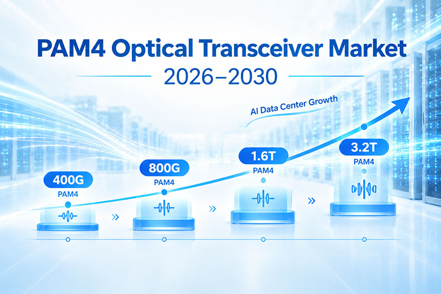
Moving from 400G to 800G doubles aggregate port bandwidth. This can reduce port count for a target capacity, but it also increases the performance requirements of every part of the link.
7. 800G to 1.6T
1.6T increases the bandwidth per port again and commonly relies on 200G-class lanes. At this level, electrical signal integrity, optical integration, power efficiency, and thermal design become increasingly important.
8. Electrical Signal Integrity
High-speed optical modules still depend on an electrical path between the switching ASIC and optical engine. PCB traces, packages, connectors, and module interfaces introduce insertion loss, reflections, crosstalk, and other impairments.
9. SerDes as a Bottleneck
The host SerDes determines the electrical signal quality available to the optical module. If the host channel cannot maintain sufficient eye opening and margin at the required lane rate, increasing optical bandwidth alone will not solve the problem.
10. Connector Loss and Reflections
High-speed electrical connectors can become significant signal-integrity elements at 100G-class and 200G-class lane rates. Poor impedance control or connector discontinuities can reduce the available margin before the signal reaches the optical engine.
11. Optical Engine Limitations
The optical engine must convert increasingly fast electrical lanes into optical signals while meeting output-power, eye-quality, BER, and thermal requirements. Modulators, lasers, photodetectors, drivers, and TIAs all contribute to the final performance.
12. DSP as a Power Bottleneck
In conventional retimed optical modules, DSP can be a major power-consuming component. As module bandwidth increases, DSP efficiency becomes increasingly important for controlling module power and heat.
13. LPO as a Response
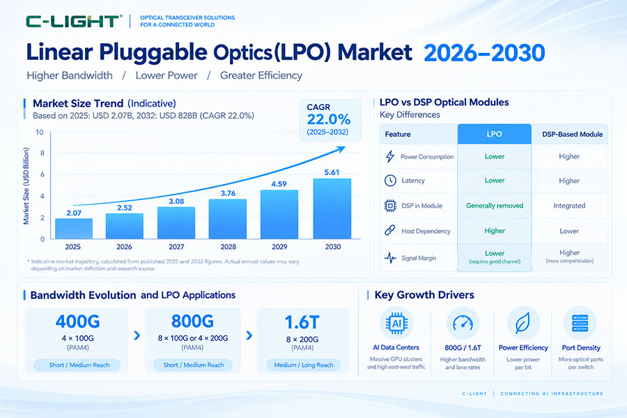
Linear-drive Pluggable Optics reduces or bypasses selected module-level DSP functions and relies more heavily on the host electrical system. This can reduce module power and latency in suitable implementations, but it places tighter requirements on the electrical channel and host SerDes.
14. CPO as a Response
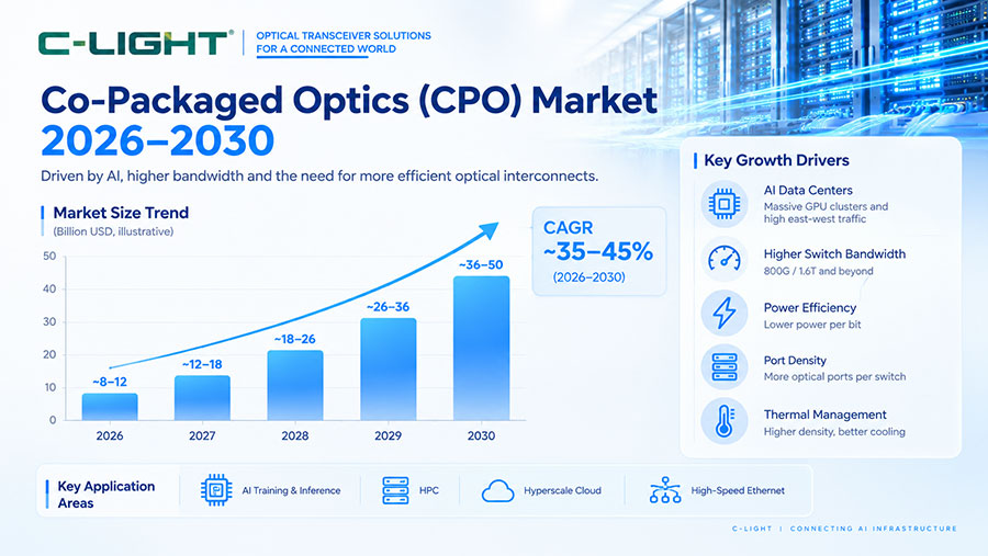
Co-Packaged Optics moves optical engines much closer to the switching ASIC. The shorter electrical path can reduce some of the loss and power associated with high-speed electrical interconnects, but CPO introduces new thermal, packaging, manufacturing, and serviceability challenges.
15. Silicon Photonics
Silicon photonics can integrate waveguides, modulators, wavelength filters, multiplexers, and photodetectors into a compact photonic integrated circuit. This can improve optical integration and support high-density multi-channel designs.
16. Optical Reach Bottlenecks
Not every AI link has the same physical distance. Short GPU-to-switch connections may require only tens or hundreds of meters, while links between different zones or facilities can require kilometers. Using an optical architecture designed for the wrong reach can create unnecessary cost, power, or performance limitations.
17. Short-Reach Bottlenecks
Short-reach links are often constrained by port density, cable management, thermal load, and electrical signal integrity rather than fiber distance. High-density switches may require many optical connections within a small physical space.
18. Medium-Reach Bottlenecks
Links extending across racks or rows can move beyond the most practical range of some short-reach architectures. Single-mode solutions such as DR-class optics can provide a longer optical reach while maintaining high bandwidth.
19. Long-Reach Bottlenecks
Longer links consume more optical budget through fiber attenuation, connector loss, and passive components. As distance increases, receiver sensitivity, optical power, dispersion, and link margin become more important.
20. Fiber Loss
Fiber attenuation reduces received optical power as the transmission distance increases. A link that works easily at a short distance may approach its optical margin when additional fiber, connectors, or patch panels are introduced.
21. Optical Link Budget
A complete link-budget calculation should include transmitter output, receiver sensitivity, fiber attenuation, connector loss, splice loss, and other passive optical components. The available margin should be sufficient for expected installation and operating variations.
22. Fiber Density
High-bandwidth AI networks can require large numbers of optical fibers. Parallel optical architectures increase fiber count, while WDM architectures can combine multiple wavelengths over fewer fibers. The fiber architecture therefore affects both connectivity and physical infrastructure.
23. MPO and High-Density Cabling
MPO-based systems support dense parallel optical connections, but they introduce requirements for fiber count, polarity, lane mapping, and connector cleanliness. Incorrect polarity can prevent an otherwise healthy optical system from establishing a link.
24. WDM as a Scaling Method
Wavelength division multiplexing allows multiple optical channels to share a fiber pair. This is useful for architectures such as FR4 and LR4 and can become increasingly important when fiber availability is limited.
25. Thermal Bottlenecks
Optical transceivers convert electrical power into heat. In a switch with many high-speed modules, the combined thermal load can become significant. Cooling therefore has to be considered at module, switch, rack, and facility levels.
26. Air Cooling Limits
Air-cooled systems depend on heat sinks, airflow, fans, and facility cooling. Higher module density can require higher airflow and fan power, while local hotspots can reduce available thermal margin.
27. Liquid Cooling
Liquid cooling can provide stronger heat-transfer capability for high-density systems. Cold-plate, direct-to-chip, and immersion architectures are different approaches, and optical modules must be designed or qualified for the selected cooling environment.
28. Optical Reliability
AI clusters depend on large numbers of optical connections operating continuously. A single degraded link can introduce errors, retransmissions, or reduced traffic efficiency, making optical reliability important at cluster scale.
29. BER and FEC
Bit Error Rate is a fundamental indicator of link quality. FEC can correct certain transmission errors, but increasing corrected-error counts may indicate that a link is operating with reduced margin.
30. Temperature and Optical Performance
Temperature can affect lasers, drivers, receivers, and electronic processing. Changes in optical power, wavelength, bias, or receiver behavior can reduce link margin when a module operates near its thermal limits.
31. Interoperability Bottlenecks
An optical module must work with the host switch or NIC, fiber system, cable, firmware, and management interface. Matching the same nominal data rate does not guarantee interoperability.
32. Vendor Coding and Management
Host devices may read module identification information before enabling a port. EEPROM data, vendor coding, management standards, and software support can therefore affect whether a transceiver is accepted.
33. Optical Module Qualification
High-speed AI networks require more than basic link-up testing. Qualification should include sustained traffic, BER, FEC counters, optical power, temperature, lane performance, interoperability, and long-duration operation.
34. Network Topology
Optical bottlenecks can also result from network architecture rather than the module itself. Oversubscription, insufficient uplink capacity, unbalanced traffic, and limited switch radix can prevent GPUs from receiving the bandwidth available at the physical optical layer.
35. GPU Utilization
A fast optical link does not automatically guarantee high GPU utilization. Network congestion, latency, packet loss, synchronization traffic, and topology can still cause compute resources to spend time waiting for data.
36. Optical Latency
Optical transmission introduces very little propagation delay compared with electrical processing and switching, but the complete link may include DSP, retiming, serialization, buffering, and other processing stages. Architecture therefore matters when evaluating latency.
37. Power per Bit
Power per bit is a useful metric when comparing optical generations. An 800G or 1.6T module may consume more absolute power than an earlier-generation module while still delivering better energy efficiency per transmitted bit.
38. Common Bottleneck by Network Scenario
| Scenario | Potential Optical Bottleneck |
|---|---|
| GPU-to-switch | Electrical channel, module power, thermal density |
| Leaf-to-spine | Port bandwidth, fiber density, link margin |
| Large AI cluster | Interoperability, reliability, congestion, scale |
| Long DCI | Optical budget, OSNR, dispersion, reach |
| High-density switch | Thermal load, power, connector density |
39. How to Reduce Optical Bottlenecks
Solutions include increasing bandwidth per port, selecting the correct optical reach, improving electrical signal integrity, reducing module power, optimizing cooling, using higher-integration optical engines, and implementing appropriate LPO or CPO architectures where supported.
40. Optical Bottleneck Prevention Checklist
Before deployment, verify host SerDes capability, optical module bandwidth, reach, fiber type, connector, optical budget, lane mapping, polarity, module power, thermal limits, coding, management, FEC behavior, interoperability, and sustained-traffic performance.
41. Frequently Asked Questions
Q1. What are the main optical bottlenecks in AI data centers?
Q2. Does increasing optical bandwidth solve AI network bottlenecks?
Q3. Why is 800G important for AI data centers?
Q4. Why is 1.6T more difficult to deploy?
Q5. Can LPO reduce optical bottlenecks?
Q6. Can CPO reduce optical bottlenecks?
Q7. Why does fiber type matter?
Q8. What happens when optical margin is too low?
Q9. Is thermal management an optical bottleneck?
Q10. How can AI data centers prevent optical bottlenecks?
42. Summary
Optical bottlenecks in AI data centers are created by the interaction of bandwidth, electrical signal integrity, optical performance, power, thermal management, fiber infrastructure, reliability, and network architecture. The move from 400G to 800G and 1.6T increases the pressure on every part of the optical link, making higher integration and better power efficiency increasingly important. Technologies such as silicon photonics, LPO, and CPO can address specific limitations, but none eliminates the need for careful system-level design. A reliable AI optical network must therefore evaluate the complete path from switch ASIC and SerDes to optical engine, fiber infrastructure, remote endpoint, cooling system, and network topology.
 >
>

 >
>
 >
>
 >
>
 >
>
 >
>
 >
>
 >
>