TEL:+86 132 6656 7067




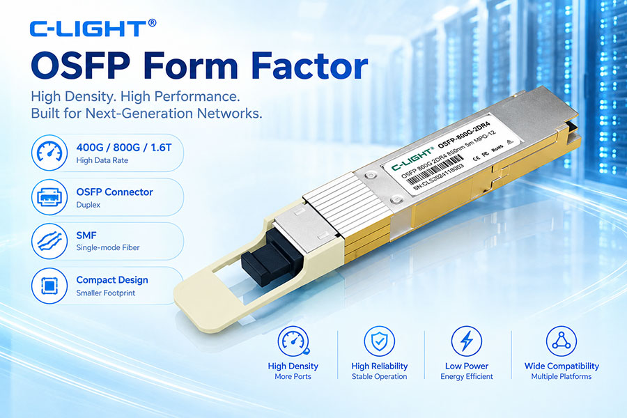
OSFP, or Octal Small Form Factor Pluggable, is a high-speed pluggable form factor developed for high-bandwidth networking applications. It provides an eight-lane host electrical interface and was designed to support the rapid transition from 400G to 800G and 1.6T connectivity.
Compared with traditional QSFP-family modules, OSFP uses a larger mechanical package and integrates a dedicated thermal solution into the standard module design. This combination provides additional thermal capacity while maintaining high front-panel port density, making OSFP an important form factor for modern data centers, AI networks, high-performance computing, and high-speed Ethernet.
1. What Is the OSFP Form Factor?
OSFP stands for Octal Small Form Factor Pluggable. It is a pluggable module architecture defined by the OSFP Multi Source Agreement (MSA), covering the module, host cage, connector, electrical interface, mechanical structure, and thermal requirements.
The "Octal" designation reflects the eight high-speed electrical lanes supported by the interface. Depending on the generation, these lanes can operate at different signaling rates to provide 400G, 800G, or 1.6T aggregate bandwidth.
OSFP is a form factor rather than a specific optical transmission standard. Different optical technologies, connector types, cable assemblies, and transmission architectures can be implemented within the OSFP platform.
2. Why Was OSFP Developed?
The continued growth of switch ASIC bandwidth created a need for pluggable interfaces capable of supporting higher aggregate throughput while maintaining manageable thermal performance and high port density.
OSFP was designed from the beginning as a high-speed platform with sufficient mechanical and thermal capability for successive generations of networking technology. The original architecture supports 400G-class operation, while later specifications extend the platform to 800G and 1.6T.
Instead of relying only on higher electrical lane rates, the OSFP ecosystem also provides mechanical and thermal features that allow the module platform to evolve with increasing power and bandwidth requirements.
3. OSFP Eight-Lane Architecture
The OSFP host interface consists of eight high-speed transmit differential pairs and eight high-speed receive differential pairs. These lanes can operate as one eight-lane interface or be divided into multiple lower-width port configurations depending on the capabilities of the host ASIC.
| OSFP Generation | Electrical Signaling | Lane Rate | Aggregate Bandwidth |
|---|---|---|---|
| OSFP 400G | 56G-PAM4 | 50 Gb/s per lane | 400G |
| OSFP800 | 112G-PAM4 | 100 Gb/s per lane | 800G |
| OSFP1600 | 224G-PAM4 | 200 Gb/s per lane | 1.6T |
The OSFP MSA Rev. 5.22 specifies 400GAUI-8, 800GAUI-8, and 1.6TAUI-8 electrical modes. The corresponding signaling classes are 56G-PAM4, 112G-PAM4, and 224G-PAM4, respectively.
4. How Does OSFP Scale from 400G to 1.6T?
The bandwidth evolution of OSFP is closely tied to electrical lane speed. A 400G implementation uses eight 50 Gb/s-class lanes, while an 800G implementation increases the lane rate to 100 Gb/s-class. OSFP1600 then increases the electrical interface to 200 Gb/s-class per lane.
This approach allows aggregate bandwidth to increase without multiplying the number of host electrical lanes. The result is a scalable architecture that can remain compatible with the general eight-lane concept while electrical signaling technologies continue to advance.
At the 1.6T level, this requires significantly higher electrical performance from the switch ASIC, PCB, connector, module package, and optical engine.
5. OSFP and PAM4 Signaling
PAM4, or four-level pulse amplitude modulation, is a key technology used in high-speed OSFP implementations. PAM4 uses four signal levels to transmit two bits per symbol, allowing higher bit rates without requiring the same proportional increase in symbol rate.
OSFP 800G systems commonly use 112G-PAM4 electrical signaling, while OSFP1600 uses 224G-PAM4 signaling. These higher-speed electrical interfaces provide the bandwidth required by next-generation switch platforms.
However, PAM4 has smaller voltage separation between signal levels than NRZ. This makes the electrical channel more sensitive to noise, crosstalk, insertion loss, reflections, and other impairments.
6. OSFP Mechanical Design
The OSFP module has a larger mechanical envelope than traditional QSFP-family modules. This additional space supports high-speed electrical components, optical components, and a larger thermal structure.
A standard OSFP module incorporates an integrated heat sink. The OSFP MSA defines both closed-top and open-top heat sink structures, allowing the cooling design to be adapted to different module and system requirements.
The mechanical system includes the module housing, cage, connector, latch mechanism, PCB interface, thermal surfaces, and airflow path. These components must work together to maintain mechanical reliability and high-speed electrical performance.
7. OSFP Integrated Heat Sink
One of the most recognizable features of OSFP is its integrated heat sink. Unlike many earlier pluggable modules where thermal solutions are relatively limited, OSFP provides a larger cooling structure directly as part of the module design.
The integrated heat sink increases the available thermal surface area and provides a defined path for heat transfer into the system airflow. This is particularly important as 800G and 1.6T modules require higher power levels than earlier generations.
The OSFP MSA includes detailed requirements for heat sink geometry, airflow, thermal contact, and module operating conditions to support high-power applications.
8. What Is OSFP-RHS?
OSFP-RHS stands for OSFP with a riding heat sink. Unlike the standard OSFP module, OSFP-RHS does not include an integrated heat sink. Instead, the module makes thermal contact with a separate heat sink located in the host system.
This design provides greater flexibility for systems with specific cooling architectures. The host can use its own thermal structure rather than relying on a heat sink integrated into every module.
OSFP and OSFP-RHS share the same electrical and management specifications, but their mechanical interfaces are different. A standard OSFP module is not mechanically interchangeable with an OSFP-RHS port.
9. OSFP Electrical Connector
The OSFP electrical interface provides eight high-speed transmit and eight high-speed receive differential pairs, together with low-speed management and control signals, power, and ground connections.
The high-speed interface supports multiple port configurations depending on the host ASIC. An OSFP port can operate as a single eight-lane connection or be divided into dual, quad, or individual lane configurations for breakout applications.
This flexibility allows the same physical port architecture to support different networking topologies and host-side configurations.
10. OSFP Host-Side Signal Integrity
High-speed OSFP performance depends heavily on the complete electrical channel between the switch ASIC and the module. The channel includes package structures, PCB traces, vias, connectors, cage interfaces, module contacts, and internal module circuits.
As lane speeds move from 56G-PAM4 to 112G-PAM4 and 224G-PAM4, the available signal margin becomes increasingly sensitive to channel loss and distortion.
PCB material, trace length, connector loss, return loss, impedance control, via transitions, crosstalk, and equalization must therefore be carefully considered when designing the host platform.
11. OSFP Thermal Management
Thermal management is one of the major design considerations for high-speed OSFP modules. Optical engines, drivers, DSPs, retimers, and other active components can contribute significantly to module power consumption.
The integrated heat sink of standard OSFP modules is designed to transfer heat from the module into the system airflow. Host cage design and airflow conditions are also important because the thermal performance of the module depends on the complete cooling environment.
The OSFP specification Rev. 5.22 includes thermal requirements for the module and cage system and provides high-flow heat sink examples for high-power applications.
12. OSFP Power Consumption
OSFP power consumption varies according to the module architecture and components used. Optical reach, laser technology, DSP architecture, signal conditioning, and operating conditions can all affect total power.
As the industry moves to 800G and 1.6T, higher electrical lane rates and more advanced optical engines increase the importance of power efficiency.
The latest OSFP1600 specification defines a maximum module power level of 42.9 W, reflecting the greater thermal and electrical requirements of the 1.6T generation.
13. OSFP Optical Architecture
OSFP is not tied to one optical architecture. Depending on the transmission standard, an OSFP module can use parallel optical channels, wavelength multiplexing, or other optical configurations.
Parallel architectures can provide multiple independent optical channels through MPO/MTP or other multi-fiber connectors. Wavelength-multiplexed architectures can combine multiple optical wavelengths into duplex fiber connections.
This flexibility allows OSFP to support both short-reach data center links and longer single-mode fiber applications.
14. OSFP Optical Connectors
Different OSFP optical modules can use different connector types according to the optical architecture. MPO/MTP connectors are common for parallel-fiber implementations, while duplex LC can be used for wavelength-multiplexed solutions.
Other high-density connector technologies are also supported by the OSFP ecosystem. The OSFP specification includes multiple connector and lane-mapping configurations for different optical PMDs.
Connector selection should therefore be based on the optical standard, number of fibers, transmission distance, and the cabling architecture of the network.
15. OSFP 400G Applications
400G OSFP provides an eight-lane 50G-class electrical interface and can be used for high-speed Ethernet and data center connectivity.
Typical applications include switch-to-switch links, server connectivity, data center interconnects, and high-performance computing systems. Depending on the optical PMD, 400G OSFP can support different reach and fiber configurations.
The 400G generation also provides the foundation for migration toward 800G and higher-speed OSFP platforms.
16. OSFP 800G Applications
800G is one of the most important OSFP applications in current high-density networking. OSFP800 uses eight 100G-class electrical lanes and is designed for high-bandwidth switch platforms and data center networks.
800G OSFP modules can be implemented with different optical architectures, including short-reach, parallel single-mode, and wavelength-multiplexed solutions.
Because 800G modules can deliver high bandwidth through a single pluggable port, they are particularly suitable for high-density leaf-spine networks, AI clusters, and high-performance data center switches.
17. OSFP1600 and 1.6T Networking
OSFP1600 extends the platform to 1.6T by using eight 200G-class electrical lanes. According to the OSFP MSA specification, 1.6TAUI-8 uses 224G-PAM4 signaling and provides eight 200 Gb/s lanes for a total of 1.6 Tb/s.
The same eight-lane host interface can be mapped to different PMD configurations, including 1x1.6T, 2x800G, 4x400G, or 8x200G depending on the host and module architecture.
This makes OSFP1600 relevant to future switch platforms requiring very high aggregate bandwidth and flexible breakout capabilities.
18. OSFP Breakout Architecture
One important capability of OSFP is lane-level breakout. Because the electrical interface contains eight high-speed lanes, compatible systems can divide a high-bandwidth port into multiple lower-speed connections.
For example, the OSFP electrical specification allows the eight-lane interface to be configured for dual four-lane, quad two-lane, or individual lane operation. The actual breakout capability depends on the switch ASIC, module, cable, optical PMD, and network software.
Breakout can simplify network design by allowing a high-bandwidth switch port to connect to multiple lower-speed interfaces.
19. OSFP DAC and AOC
OSFP is not limited to optical transceivers. The form factor can also be used for high-speed DAC and AOC solutions.
OSFP DACs are suitable for short-distance connections where a direct electrical connection provides a simple and cost-effective interconnect. OSFP AOCs use optical transmission within the cable assembly and can support longer distances than passive copper solutions.
These cable-based options are commonly considered for switch-to-switch, server, and rack-scale interconnects where the required distance is relatively short.
20. OSFP in AI and HPC Networks
AI and high-performance computing networks generate substantial traffic between GPUs, accelerators, servers, switches, and storage systems. This creates increasing demand for high-bandwidth, low-latency, and high-density network interfaces.
OSFP is well suited to these environments because the eight-lane architecture can support 400G, 800G, and 1.6T generations while the integrated heat sink provides additional thermal capability for high-power modules.
In AI clusters, OSFP optical transceivers and active or passive cables can be used for different parts of the network depending on distance, topology, and bandwidth requirements.
21. OSFP and Data Center Port Density
Although OSFP is physically larger than QSFP-family modules, it remains a high-density pluggable form factor. The larger package provides additional room for thermal management while still allowing a large number of high-speed ports to be installed on modern switch front panels.
The OSFP MSA states that up to 36 OSFP ports can be supported on a 1U front panel, depending on the system design.
This combination of bandwidth and port density is particularly important for high-capacity switch platforms.
22. OSFP Management and CMIS
The OSFP hardware specification defines the physical and electrical aspects of the module, while module management is handled through the Common Management Interface Specification, or CMIS.
Management functions allow the host system to identify the module, configure supported applications, monitor operating conditions, and retrieve diagnostic information.
Depending on the implementation, management information can include module identification, temperature, voltage, optical power, alarms, and other operating parameters.
23. OSFP Module Monitoring
Monitoring functions are important for maintaining high-speed links and identifying potential problems before they affect network availability.
Common monitored parameters can include module temperature, supply voltage, transmit optical power, receive optical power, and other diagnostic information supported by the module and host platform.
These measurements help network operators validate link conditions and troubleshoot optical or thermal issues in high-density systems.
24. OSFP Compatibility
Physical insertion is only one part of OSFP compatibility. The host switch must also support the required electrical signaling, power level, management interface, optical standard, and operating mode.
For 800G and 1.6T applications, host-side SerDes capabilities are particularly important because the electrical interface operates at very high signaling rates.
Module coding and firmware support may also affect interoperability in multi-vendor network environments.
25. OSFP vs. QSFP-DD
OSFP and QSFP-DD are both high-speed pluggable form factors used for data center networking, but their mechanical designs and thermal approaches are different.
| Feature | OSFP | QSFP-DD |
|---|---|---|
| Host Electrical Lanes | 8 lanes | Up to 8 lanes |
| Common High-Speed Generations | 400G / 800G / 1.6T | 400G / 800G / 1.6T |
| Mechanical Size | Larger | More compact |
| Integrated Heat Sink | Standard OSFP includes integrated heat sink | Thermal design varies by implementation |
| Thermal Capacity | Designed for high-power applications | Depends on module and host design |
| Typical Applications | High-density 400G/800G/1.6T networking | High-density 400G/800G/1.6T networking |
The main distinction is not simply bandwidth. OSFP uses a larger package with a strong focus on thermal capability, while QSFP-DD maintains a more compact QSFP-derived mechanical architecture.
26. OSFP vs. QSFP112
OSFP and QSFP112 can both be used in 400G-class networking, but they use different mechanical and electrical approaches.
QSFP112 is a compact four-lane QSFP-family architecture using 112G-class electrical signaling, while OSFP 400G uses eight 50G-class electrical lanes. OSFP800 then moves to eight 100G-class lanes.
This means that the two form factors can deliver similar aggregate bandwidth while relying on different lane architectures and mechanical designs.
27. OSFP Advantages
One of the main advantages of OSFP is its ability to combine high bandwidth with a thermal structure designed for demanding applications.
The eight-lane electrical architecture supports multiple generations of networking bandwidth. The larger module package also provides more room for heat dissipation and advanced optical or electrical components.
Another advantage is the range of supported optical and cable configurations, allowing OSFP to serve short-reach, medium-reach, and longer-reach applications depending on the module design.
28. OSFP Design Challenges
High bandwidth does not eliminate design challenges. At 800G and 1.6T, electrical channel loss, crosstalk, connector performance, module power, heat dissipation, and system airflow become increasingly important.
Higher-rate PAM4 also requires tighter signal margins than earlier electrical interfaces. As a result, module performance depends on both the transceiver and the host platform.
For high-density deployments, thermal spacing and airflow must also be considered together with the number of active modules installed in the chassis.
29. What to Consider When Choosing an OSFP Module
Choosing an OSFP module requires more than checking the nominal data rate. The host switch should be verified for the required OSFP generation, electrical lane rate, power class, management interface, and supported module applications.
For the optical side, transmission distance, fiber type, wavelength, optical connector, link budget, and interoperability should be matched to the network design.
For 800G and 1.6T deployments, thermal conditions and system airflow are especially important because high-power modules can have a significant impact on chassis cooling requirements.
30. Future Development of the OSFP Ecosystem
The OSFP ecosystem continues to evolve with increasing network bandwidth. The transition from 400G to 800G and 1.6T demonstrates how the same general eight-lane architecture can support higher electrical rates as switch and optical technologies advance.
Future development will require coordinated improvements in SerDes, optical engines, packaging, connectors, PCB materials, signal processing, and thermal systems.
The OSFP platform is positioned to remain relevant as high-bandwidth networking moves toward increasingly dense switch architectures and AI-oriented infrastructure.
31. Conclusion
OSFP is a high-density pluggable form factor designed around an eight-lane electrical interface and intended for successive generations of high-speed networking. From 400G to 800G and 1.6T, the platform provides a scalable path for increasing bandwidth while maintaining a compact, serviceable pluggable architecture.
Its larger mechanical package and integrated heat sink distinguish OSFP from smaller QSFP-family solutions and provide additional thermal capability for high-power optical modules. At the same time, multiple optical, electrical, and cable configurations allow OSFP to address different networking requirements.
For modern data centers, AI clusters, high-performance computing, and high-capacity Ethernet networks, OSFP provides a flexible platform for deploying high-bandwidth connectivity while balancing electrical performance, thermal management, port density, and interoperability.
 >
>

 >
>
 >
>
 >
>
 >
>
 >
>
 >
>
 >
>