TEL:+86 132 6656 7067





MTP-12 and MTP-16 are designed around different fiber counts and connector interfaces. MTP-12 has 12 fiber positions in a single row and is widely used in established parallel-optics and structured-cabling systems. MTP-16 provides 16 positions in a single row and is suited to optical interfaces that require eight transmit fibers and eight receive fibers.
The critical distinction is not simply four additional fibers. The MPO-12 and MPO-16 interface formats use different key positioning, so they are not directly interchangeable. For 400G and 800G parallel-optics links, selecting the correct connector, fiber mapping and optical specification is essential to reliable deployment.
1. Physical Structure: 12 Fibers vs 16 Fibers
Both connector formats arrange their fiber positions in a single row, but their ferrule layouts and keying differ. The fiber count determines the number of physical optical paths available at the connection; it does not independently determine data rate, transmission distance or optical performance.
MTP-12: 12 Fiber Positions
Illustrative eight-active-fiber mapping: positions 1–4 and 9–12 are active, while the middle four positions are unused. Actual mapping must follow the transceiver specification.
MTP-16: 16 Fiber Positions
All 16 positions can be used by interfaces with eight transmit and eight receive fibers, such as common SR8 parallel-optics configurations.
The illustrations show fiber-position counts and a representative channel allocation; they are not mechanical drawings. Actual connector key orientation, guide-pin configuration, fiber numbering and end-face specifications must be confirmed against the selected cable assembly and transceiver documentation.
2. MTP-12 vs MTP-16: Technical Comparison
| Attribute | MTP-12 | MTP-16 | Deployment Impact |
|---|---|---|---|
| Nominal fiber count | 12 | 16 | MTP-16 provides four more fiber positions per connector. |
| Fiber arrangement | One row of 12 | One row of 16 | Both are single-row arrays, but their ferrule geometry and keying are not identical. |
| Key position | Centered key arrangement | Offset key arrangement | The different key positions prevent direct insertion of the wrong connector format into the corresponding interface. |
| Common optical role | 40GBASE-SR4, 100GBASE-SR4 and certain eight-fiber single-mode interfaces | 400GBASE-SR8 and other interfaces requiring 16 optical fibers | The transceiver datasheet defines the required interface. |
| Eight-fiber mapping | Can carry eight active fibers with other positions unused | Can carry eight active fibers, but leaves more positions unused if only eight are required | Use the connector specified for the equipment, rather than choosing by active fiber count alone. |
| 16-fiber parallel optics | Insufficient physical positions for a single 16-fiber connection | Supports 16 fiber positions in one connector | Relevant to eight-transmit/eight-receive optical interfaces. |
| Breakout by fiber count | Up to six duplex pairs | Up to eight duplex pairs | Theoretical counts; usable circuits depend on polarity, port mapping and the application. |
| Existing infrastructure | Fits compatible MPO-12 panels, trunks and cassettes | Requires MPO-16-compatible interfaces and distribution components | Migration may require new patch leads, adapters, trunks or cassettes. |
3. Why MTP-16 Matters for 400G and 800G Networks
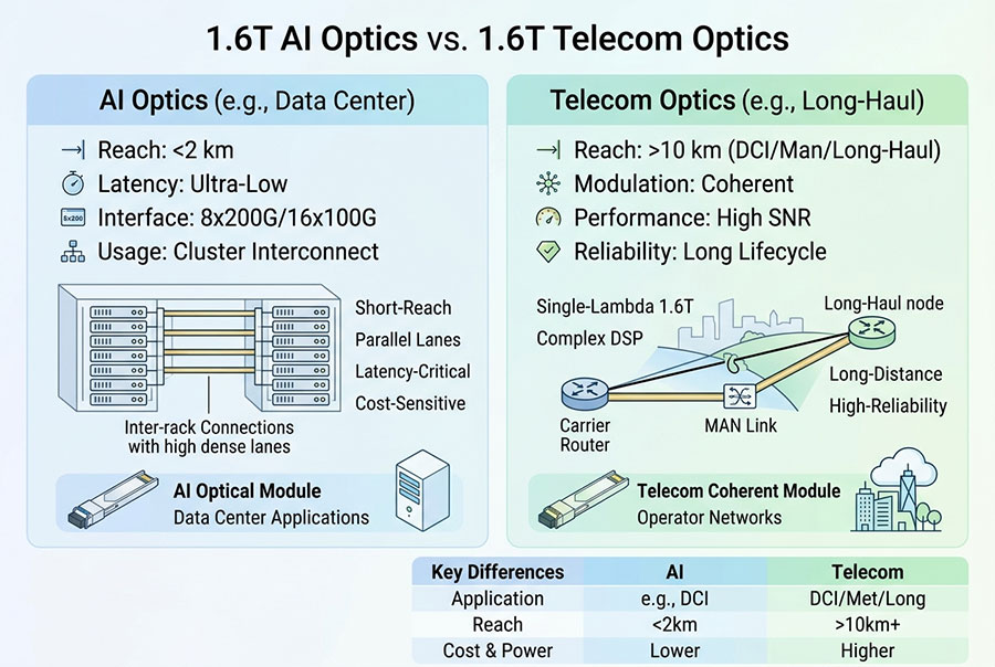
As parallel-optics interfaces increase their optical lane count, connector selection must accommodate both the transmit and receive paths. A common 400GBASE-SR8 interface uses eight transmit fibers and eight receive fibers, requiring 16 optical fibers. MTP-16 provides those positions in one connector.
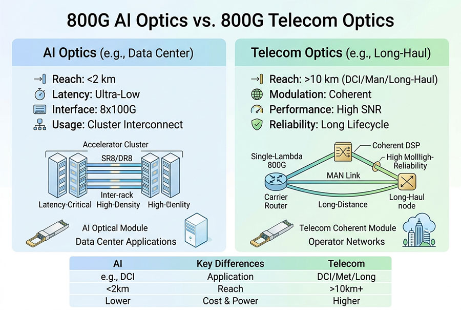
For 800G applications, the interface specification is equally important. 800GBASE-SR8 uses 16 optical fibers, and 800GBASE-DR8 also uses 16 optical fibers in common implementations. The required fiber type, connector polish and exact mapping vary with the optical standard and transceiver design.
| Optical Application | Representative Fiber Mapping | Connector Consideration |
|---|---|---|
| 40GBASE-SR4 | 4 Tx + 4 Rx = 8 active fibers | Commonly uses MPO-12 with eight active positions. |
| 100GBASE-SR4 | 4 Tx + 4 Rx = 8 active fibers | Commonly uses MPO-12; verify the specified cable mapping. |
| 400GBASE-DR4 | 4 Tx + 4 Rx = 8 optical fibers | Commonly uses a 12-position MPO interface with eight active fibers; check the module specification. |
| 400GBASE-SR8 | 8 Tx + 8 Rx = 16 optical fibers | MPO-16 is the typical parallel-optics interface. |
| 800GBASE-SR8 | 8 Tx + 8 Rx = 16 optical fibers | Requires a compatible 16-fiber parallel-optics interface. |
| 800GBASE-DR8 | 8 Tx + 8 Rx = 16 optical fibers | Common implementations use MPO-16; confirm single-mode fiber and end-face requirements. |
| 400G FR4 or LR4 wavelength-multiplexed link | Typically one transmit and one receive fiber | Many implementations use duplex LC rather than MPO-12 or MPO-16. |
These examples illustrate why aggregate bandwidth does not dictate one universal connector. Some 400G and 800G modules use parallel optical lanes, while wavelength-multiplexed interfaces can use a duplex fiber pair. The transceiver standard and manufacturer specification must determine the physical interface.
4. Connector Keying and Mechanical Compatibility
The difference in key position is one of the most consequential distinctions between MPO-12 and MPO-16. MPO-12 uses a centered key arrangement, while MPO-16 uses an offset key arrangement. This prevents the two connector formats from being directly mated in the wrong interface.
Do not attempt to force a connector into an incompatible adapter or receptacle. Doing so can damage the connector, ferrule or equipment interface. When changing from a 12-fiber cabling system to a 16-fiber transceiver, specify the required MPO-16 cable assembly, compatible panel components and end-to-end fiber mapping.
Connector gender: Verify guide pins and guide holes at both ends. The connector must mate with the transceiver receptacle or adapter as specified.
Key orientation: Confirm the connector's key position and viewing direction in the assembly drawing.
Fiber type: Match multimode or single-mode media to the optical interface. OM4 and OS2, for example, are not interchangeable simply because their connectors have the same fiber count.
End-face polish: Verify UPC/PC or APC requirements. Many parallel single-mode interfaces specify APC, while multimode interfaces commonly use flat end faces.
Polarity: Confirm that transmit fibers at one end reach the intended receive fibers at the other end.
Insertion loss: Check the cable assembly's specified loss and the total link budget, including every mated connection.
5. Base-12 to Base-16 Cabling Migration
A Base-12 cabling plant can support many established optical interfaces, but it does not automatically provide a direct connection for equipment requiring MPO-16. The migration plan should account for trunk count, patch-panel space, cassette compatibility, connector keying, polarity and test access.
Retaining the Existing MPO-12 Infrastructure
For equipment that specifies an MPO-12 interface, retaining compatible Base-12 trunks and cassettes can reduce replacement work. This is especially relevant when adding capacity to an established 40G, 100G or supported eight-fiber optical deployment. The installed fiber map should still be checked against the new transceiver's requirements.
Introducing MPO-16 for 16-Fiber Interfaces
Where a transceiver requires 16 active optical fibers through an MPO-16 interface, use an appropriate 16-fiber cable and distribution architecture. Depending on the design, this may involve new MPO-16 trunks, patch panels, adapters or harnesses. A purpose-designed conversion assembly may connect different distribution formats, but it must preserve all required optical paths and meet the link's loss budget.
6. Polarity and Optical Link Validation
A 16-fiber connector introduces more optical paths to document and test than an eight-active-fiber mapping. For SR8 and DR8 links, each transmit and receive path must reach its intended destination. A correct connector fit does not prove that the fiber sequence or polarity is correct.
Map every position: Document the transmit and receive positions at both ends of the link. Do not assume the mapping from the connector count alone.
Specify the polarity method: Identify the selected trunk and breakout mapping. Method A, B and C are different approaches and must not be mixed without a designed transition.
Inspect the end faces: Contamination across a multi-fiber ferrule can affect several channels at once. Inspect and clean the connectors using suitable procedures before mating.
Test continuity and loss: Verify the individual fiber paths and end-to-end insertion loss against the system requirements.
Confirm optical operation: After installation, validate link status and review module diagnostics where available. Do not rely on visual continuity alone.
Maintain records: Label the trunk, port, fiber type, polarity and destination so future moves and upgrades preserve the intended connection.
7. Selecting MTP-12 or MTP-16 for a New Build
The best choice depends on the actual optical interface and the cabling architecture around it. MTP-12 is often the practical option for established 12-fiber distribution and compatible lower-lane-count parallel optics. MTP-16 is the appropriate direction when a specified interface requires 16 optical fibers through a compatible 16-position connector.
| Design Requirement | Preferred Evaluation | Reason |
|---|---|---|
| Existing 12-fiber trunks and cassettes | Retain compatible MPO-12 components where the new optical interface permits | Preserves existing infrastructure and reduces unnecessary changes. |
| 400GBASE-SR8 link | Specify a compatible MPO-16 assembly | The interface uses 16 optical fibers in common implementations. |
| 800GBASE-SR8 or DR8 link | Confirm the exact MPO-16 interface, fiber mode and polish | The optical standard and module specification determine the assembly. |
| Breakout to multiple duplex links | Choose a compatible harness with documented polarity | Prevents incorrect transmit/receive routing and wasted fiber positions. |
| Mixed MPO-12 and MPO-16 infrastructure | Use a purpose-designed transition component where appropriate | Maintains mechanical compatibility and the required end-to-end mapping. |
| Future capacity upgrades | Plan trunk counts, panel density and spare fibers together | Supports growth without relying on incompatible connectors or undocumented conversions. |
8. C-LIGHT Fiber Connectivity and Transceiver Resources
C-LIGHT provides product information for fiber connectivity and optical transceivers that can support high-speed network planning. For any MPO/MTP assembly, confirm the physical fiber count, connector interface, gender, fiber mode, polish and polarity against the target transceiver before procurement.
MPO-MPO Fiber Patch Cables
Review multi-fiber cable options for structured cabling and verify that the selected connector format matches the equipment and distribution system.
Optical Transceiver Portfolio
Start with the target transceiver specification to establish the required optical standard, connector, fiber type and reach.
These resources are starting points for system design. Product compatibility should be confirmed from the specific transceiver and cable datasheets; a general catalog listing does not establish that every assembly supports every 400G or 800G interface.
9. Frequently Asked Questions
Can an MTP-12 connector plug directly into an MTP-16 adapter?
No. The MPO-12 and MPO-16 interfaces have different key positions and are not directly interchangeable. A compatible, purpose-designed transition component may be used when the system design requires it.
Does MTP-16 automatically provide higher bandwidth than MTP-12?
No. MTP-16 provides 16 physical fiber positions, but actual bandwidth depends on the transceiver, optical lane rate, modulation and network standard. The higher fiber count supports interfaces that require more parallel optical paths.
Why is MTP-16 used for 400GBASE-SR8?
400GBASE-SR8 uses eight transmit and eight receive optical fibers, for a total of 16. A compatible MPO-16 interface accommodates these paths in a single connector.
Can MPO-12 support any 400G connection?
No. Some 400G interfaces use eight optical fibers through an MPO-12 interface, while 400GBASE-SR8 uses 16 fibers through MPO-16. Other 400G interfaces use duplex LC. Connector selection must follow the exact optical standard and transceiver specification.
Can an MPO-12 trunk be reused in a Base-16 system?
Not as a direct substitute for a 16-fiber connection. Reuse may be possible for selected portions of the infrastructure through a compatible, documented transition design, but an MPO-12 connector cannot provide 16 fiber positions on its own.
10. Conclusion: Match Connector Geometry to Optical Lane Requirements
MTP-12 remains useful for established 12-fiber distribution and optical interfaces designed around MPO-12. MTP-16 provides 16 fiber positions for parallel-optics applications that require eight transmit and eight receive fibers, including common 400GBASE-SR8 and 800GBASE-SR8 implementations.
The key distinction is both physical and functional: MPO-12 and MPO-16 have different key positions, and their fiber counts support different optical mappings. Select the connector from the transceiver specification, then verify fiber mode, gender, polish, polarity and insertion-loss requirements across the complete link.
For assistance with optical transceiver and fiber connectivity requirements, Contact C-LIGHT.
 >

 >
 >
 >
 >
 >
 >
 >