TEL:+86 132 6656 7067





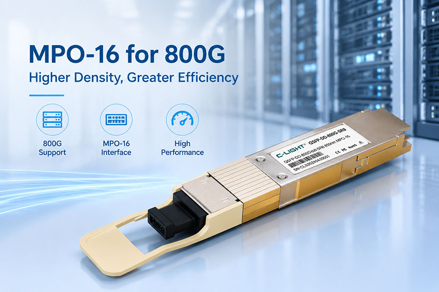
The transition to 800G Ethernet is changing the physical infrastructure of modern data centers. Higher port bandwidth requires optical interfaces that can support more parallel channels while maintaining reliable signal transmission, manageable cable density and efficient rack connectivity.
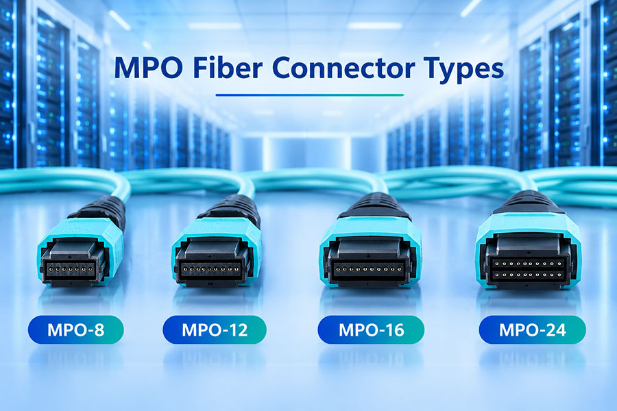
MPO-16 is an important connector format in this transition. It provides a 16-fiber interface for parallel optical transceivers, supporting eight transmit lanes and eight receive lanes in a single connector. This configuration is used by 800GBASE-SR8 and 800GBASE-DR8 applications, making MPO-16 relevant to high-density data center networks, AI infrastructure and switch-to-switch optical connections.
1. What Is an MPO-16 Connector?
MPO-16 is a multi-fiber push-on connector designed to terminate 16 optical fibers in a single connector interface. Unlike conventional duplex LC connectors, which connect two fibers, MPO-16 accommodates a complete group of parallel optical channels in one compact connection.
In an 800G parallel-optics application, the 16 fibers are generally divided into two groups:
8 transmit fibers (Tx): Carry optical signals from the local transceiver to the remote device.
8 receive fibers (Rx): Carry optical signals from the remote device back to the local transceiver.
This arrangement supports eight optical lanes in each direction. When each lane carries 100Gbps, the aggregate interface reaches 800Gbps in each transmission direction.
2. Why MPO-16 Is Used in 800G Networks
As data center switching capacity increases, parallel optical interfaces need more channels to support higher aggregate bandwidth. MPO-16 provides the fiber count required by several eight-lane 800G optical interfaces.
Using a single 16-fiber connector can also simplify cable routing compared with managing multiple separate fiber connectors. The actual benefit depends on the transceiver design and the structured cabling architecture.
3. MPO-16 Fiber Mapping for 800G
Fiber mapping defines how the optical positions inside an MPO-16 connector correspond to the transmit and receive channels of the transceiver. Correct mapping is essential because the local transmit fibers must connect to the remote receive fibers, and vice versa.
A common 800G eight-lane interface uses eight fiber positions for transmission and eight for reception. The following diagram illustrates the two groups in a simplified connector view.
Illustrative fiber grouping only. The actual Tx/Rx position orientation must be confirmed from the transceiver datasheet and connector viewing convention.
In a common MPO-16 mapping convention, the transmit and receive groups occupy opposite sides of the array. The exact pin orientation and position numbering must be checked against the module manufacturer's optical interface drawing.
For direct transceiver-to-transceiver connections, the cable must provide the correct end-to-end crossover so that Tx aligns with Rx. A connector that physically fits does not necessarily have the correct optical polarity.
4. 800G Transceivers That Use MPO-16
MPO-16 is used by several 800G parallel-optics interfaces. Two important examples are 800GBASE-SR8 and 800GBASE-DR8. Although both use 16 optical fibers, they operate over different fiber types and transmission distances.
| 800G Interface | Fiber Type | Connector | Typical Application |
|---|---|---|---|
| 800GBASE-SR8 | Multimode fiber | MPO-16 | Short-reach data center connections |
| 800GBASE-DR8 | Single-mode fiber | MPO-16 | Higher-density single-mode parallel links |
| 800GBASE-DR8-2 | Single-mode fiber | Implementation-dependent; MPO-16 or dual MPO-12 | Single-mode parallel optical connections |
| 800G 2×DR4 | Single-mode fiber | Typically 2 × MPO-12 | Dual 400G optical interfaces in one module |
| 800G 2×FR4 | Single-mode fiber | Typically dual duplex LC | Dual-wavelength-group client-side connections |
The connector is determined by the optical interface design, not simply by the 800G data rate. Therefore, an 800G module should never be assumed to use MPO-16 without checking its product specification.
5. MPO-16 for 800GBASE-SR8
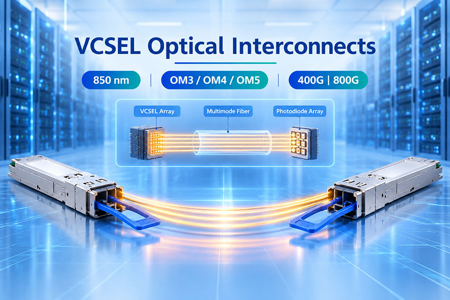
800GBASE-SR8 is a short-reach multimode optical interface designed for high-bandwidth connections inside data centers. It uses eight parallel optical lanes in each direction, with each lane carrying 100Gbps using PAM4 signaling.
The 16-fiber MPO-16 connector provides the required eight transmit and eight receive optical paths.
| Parameter | 800GBASE-SR8 |
|---|---|
| Aggregate data rate | 800Gbps |
| Optical lanes | 8 Tx + 8 Rx |
| Per-lane signaling | 100Gbps PAM4 class |
| Fiber type | Multimode fiber |
| Wavelength region | 850nm class |
| Connector | MPO-16 |
| Typical reach | Depends on the specified multimode grade; up to 100m class on suitable OM4/OM5 systems |
SR8 is particularly useful for short-distance connections between high-capacity switches and network equipment. Its multimode fiber architecture is different from the single-mode infrastructure used by DR8.
6. MPO-16 for 800GBASE-DR8
800GBASE-DR8 is a single-mode parallel optical interface designed for higher-reach data center connections. Like SR8, it uses eight optical lanes in each direction, but the optical transmission operates over single-mode fiber.
A typical DR8 implementation uses an MPO-16 APC optical interface. Eight transmit fibers and eight receive fibers are carried through one connector, supporting a parallel single-mode connection between compatible devices.
| Parameter | 800GBASE-DR8 |
|---|---|
| Aggregate data rate | 800Gbps |
| Optical lanes | 8 Tx + 8 Rx |
| Per-lane signaling | 100Gbps PAM4 class |
| Fiber type | OS2 single-mode fiber |
| Wavelength region | 1310nm class |
| Connector | MPO-16 APC |
| Typical reach | Up to 500m for the defined DR8 application |
Because DR8 uses single-mode fiber, it is not compatible with the multimode fiber infrastructure intended for SR8. The connector format may look similar, but the fiber type and optical specifications are different.
7. MPO-16 vs. MPO-12 for 800G
MPO-12 and MPO-16 are both multi-fiber connector formats, but they have different fiber counts and physical keying arrangements. MPO-12 is commonly used in four-lane parallel optical interfaces, while MPO-16 supports eight-lane interfaces in a single connector.
| Feature | MPO-12 | MPO-16 |
|---|---|---|
| Fiber count | 12 fibers | 16 fibers |
| Common parallel interface | 4-lane optical interfaces | 8-lane optical interfaces |
| 800G application | Some dual-port or breakout implementations | 800G SR8 and DR8 interfaces |
| Fiber utilization | Depends on the optical interface; some positions may remain unused | All 16 positions can be used for 8 Tx and 8 Rx |
| Physical keying | Standard MPO-12 key position | Different key position from MPO-12 |
| Typical role | Four-lane parallel connectivity | Eight-lane parallel connectivity |
MPO-16 is not simply a larger MPO-12 that can be inserted into the same adapter. The connector geometry and key position are different. Both the connector and adapter must match the selected fiber interface.
8. MPO-16 Polarity: Type A, Type B and Type C
Polarity describes how individual fibers are connected from one end of a cable to the other. In parallel optical systems, polarity is especially important because the transmit and receive lanes must be correctly aligned between the two transceivers.
For structured cabling, polarity must be evaluated across the complete channel rather than selecting a patch cord in isolation. A trunk cable, cassette and equipment-side jumper can each change the final fiber mapping.
9. MPO-16 Connector Gender and Pin Configuration
MPO connectors are available in male and female versions. The difference is based on the presence or absence of alignment guide pins.
Male MPO connector: Contains guide pins for alignment.
Female MPO connector: Contains guide holes and does not have guide pins.
Correct gender matching is necessary when connecting MPO interfaces. In many transceiver designs, the module receptacle contains guide pins, so the mating cable connector must be female. However, this arrangement should always be confirmed from the module manufacturer's mechanical specification.
Connector gender, key orientation and polish type are separate properties. A cable can have the correct fiber count but still be unsuitable because its pin configuration or end-face type does not match the equipment.
10. MPO-16 APC vs. UPC
MPO-16 connector interfaces can have different end-face polish configurations. APC and UPC are not interchangeable connection types, and the correct polish must be selected according to the optical interface.
| Feature | UPC | APC |
|---|---|---|
| End-face design | Physical contact with a flat polished geometry | Angled physical contact, commonly 8 degrees |
| Typical appearance | Often associated with multimode MPO interfaces | Commonly used in single-mode MPO interfaces |
| 800G example | SR8 multimode applications | DR8 single-mode applications |
| Connection requirement | Must mate with a compatible UPC interface | Must mate with a compatible APC interface |
Never connect APC and UPC end faces together. A polish mismatch can result in poor optical contact, increased insertion loss and potential connector damage.
11. MPO-16 Cable Selection for 800G
Selecting an MPO-16 cable requires more than matching the connector's fiber count. The cable must meet the optical, mechanical and installation requirements of the transceiver and cabling system.
Fiber type: Choose OM4 or OM5 for supported multimode SR8 applications, or OS2 for single-mode DR8 applications.
Polish: Match the required UPC or APC interface.
Fiber count: Confirm that all 16 optical positions are populated and correctly mapped.
Gender: Verify male or female connector requirements at both ends.
Polarity: Confirm the required Type A, B or C arrangement for the complete link.
Insertion loss: Select components with sufficient loss margin for the transceiver's optical budget.
Cable construction: Consider bend radius, cable diameter, jacket rating and installation environment.
For high-density AI data center installations, factory-terminated MPO-16 trunk assemblies can help simplify deployment. However, each assembly should be tested and documented before being connected to production equipment.
12. Common MPO-16 Installation Problems
Many optical connection problems originate from physical cabling mismatches rather than the transceiver itself. Incorrect fiber mapping, contamination and incompatible connector types can prevent an otherwise functional 800G link from establishing correctly.
| Problem | Possible Cause | Recommended Check |
|---|---|---|
| Link fails to establish | Incorrect polarity or Tx/Rx mapping | Verify the complete fiber path and connector orientation. |
| High insertion loss | Contamination, damaged end faces or excessive connection loss | Inspect and clean connectors using approved procedures. |
| Connector cannot be inserted | Incorrect MPO fiber count, key orientation or gender | Check the module and adapter mechanical specifications. |
| Optical signal is unstable | Fiber damage, excessive bending or poor connection quality | Inspect the cable route and verify optical measurements. |
| Unexpected channel errors | Fiber mapping mismatch or channel-specific optical impairment | Check individual lane diagnostics and fiber continuity. |
| Incorrect optical performance | Multimode and single-mode components mixed in one link | Confirm that the complete channel uses the correct fiber type. |
13. MPO-16 in AI Data Center Networks
AI data centers use large numbers of high-speed optical connections to link switches, compute nodes and distributed network resources. As 800G Ethernet adoption expands, connector density and cable organization become increasingly important.
MPO-16 supports the parallel optical architecture used by suitable 800G SR8 and DR8 interfaces. Its 16-fiber arrangement helps consolidate multiple optical lanes into a single physical connector.
For new installations, the connector architecture should be planned alongside the transceiver roadmap. A well-designed fiber plant can support current 800G interfaces while providing a structured path toward higher-capacity optical connectivity.
14. C-LIGHT 800G Optical Connectivity Solutions
High-speed optical networks require compatible transceivers, fiber assemblies and host equipment. The connector configuration must match the optical interface rather than being selected solely by the Ethernet data rate.
800G OSFP Optical Transceivers
The C-LIGHT 800G OSFP product family supports high-speed data center connectivity across different optical interface categories.
Depending on the selected module, applications can include short-reach and parallel-optics connections. The exact connector, fiber type, transmission distance and polarity should be verified against the corresponding product specification.
800G QSFP-DD Optical Transceivers
The C-LIGHT 800G QSFP-DD product family provides high-density optical connectivity options for data center network equipment.
When planning an MPO-16 connection, confirm that the specific transceiver model supports the required 16-fiber interface and that the cable assembly matches its optical and mechanical requirements.
For projects involving MPO/MTP fiber assemblies, connector gender, fiber count, polish, polarity and insertion-loss requirements should be specified together. This helps ensure that the cabling infrastructure is compatible with the intended 800G optical interface.
15. Conclusion
MPO-16 is an important connector format for 800G parallel optical networks. By providing 16 optical fibers in one connector, it supports eight transmit and eight receive lanes used by 800GBASE-SR8 and 800GBASE-DR8 applications.
Its role extends beyond the physical connector. Fiber mapping, polarity, connector gender, end-face polish and fiber type all affect the performance and compatibility of an 800G optical link. A correct MPO-16 design must therefore be based on the exact transceiver interface and the complete cabling path.
As data centers expand toward higher-speed Ethernet and AI networking, MPO-16-based connectivity provides a practical foundation for organizing dense parallel optical connections. Proper component selection and installation validation help maintain reliable optical performance across high-capacity network environments.
Build Reliable 800G Fiber Connectivity
Choosing the right optical transceiver and MPO/MTP cabling requires attention to fiber type, connector configuration, polarity and transmission requirements. Contact C-LIGHT for product information and technical support for your high-speed optical networking project.
Contact C-LIGHT >

 >
 >
 >
 >
 >
 >
 >