TEL:+86 132 6656 7067




The rapid development of artificial intelligence (AI), high-performance computing (HPC), and hyperscale data centers is pushing optical communication systems into a new thermal era. As networks move from 400G to 800G and 1.6T, optical transceivers are integrating more optical channels, higher-speed electrical interfaces, DSPs, laser arrays, and increasingly compact packages.
This combination creates a new challenge: optical modules are becoming not only faster, but also significantly more thermally demanding. In high-density AI data centers, the thermal performance of an optical module can directly affect signal quality, operating stability, component lifetime, and the overall reliability of the network.
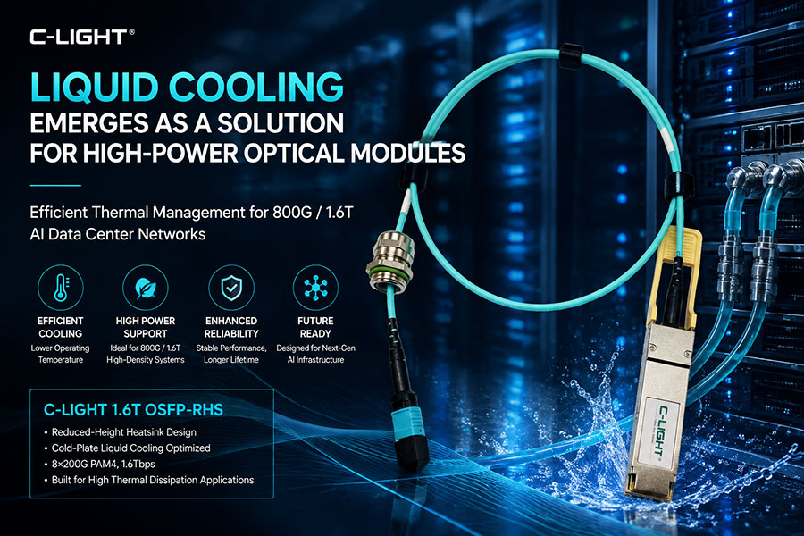
Traditional air cooling remains practical for many lower-power optical modules. However, as module power density increases, advanced thermal technologies are becoming increasingly important. Liquid cooling is emerging as one of the potential solutions for high-power 800G, 1.6T, and future optical interconnect architectures. C-LIGHT's 1.6T OSFP-RHS, for example, uses a reduced-height heatsink structure specifically optimized for advanced thermal management and integration with cold-plate liquid cooling systems.
1. Why Thermal Management Has Become a Critical Optical Module Issue
For many years, optical transceiver thermal management was relatively straightforward. Lower-speed modules typically generated modest amounts of heat, and airflow through the switch chassis could remove the heat sufficiently.
The situation changes significantly at 800G and 1.6T.
A modern high-speed optical module may contain:
High-speed DSP or retimer components
Laser arrays or EMLs
Photodetectors and TIA arrays
High-speed electrical drivers
Optical coupling structures
Advanced PCB and packaging components
When these components are concentrated into a small pluggable form factor, the challenge is no longer simply removing heat from the module. The challenge is creating an efficient thermal path from the heat-generating components to the data center cooling infrastructure.
2. AI Data Centers Are Increasing Optical Thermal Density
AI infrastructure is fundamentally different from traditional enterprise data centers. GPU clusters require extremely high-speed networking between compute nodes, switches, and storage systems.
A large AI cluster may contain a very high number of 400G, 800G, or future 1.6T optical connections. Even modest power consumption per optical interface becomes significant when multiplied across a large number of ports.
The thermal challenge therefore has two dimensions:
Module-level thermal density: More power is concentrated inside each optical transceiver.
System-level thermal density: More high-power optical interfaces are installed in a limited switch and rack footprint.
This is why optical module thermal management is increasingly becoming a system-design issue rather than an isolated component issue.
3. From 400G to 800G and 1.6T
The evolution of optical connectivity illustrates why thermal management is becoming more important.
| Generation | Typical Architecture | Thermal Challenge |
| 400G | Multiple high-speed optical lanes | Moderate-to-high power density |
| 800G | Higher-speed PAM4 optical lanes | Higher DSP and optical engine thermal load |
| 1.6T | 8×200G-class architecture | Very high thermal density and tighter cooling requirements |
| 3.2T and beyond | Higher lane speed and advanced integration | System-level thermal architecture becomes increasingly critical |
The move from 800G to 1.6T is especially important because the increase in bandwidth is accompanied by significantly more demanding electrical and optical components. C-LIGHT's 1.6T OSFP-RHS uses 8×200G PAM4 signaling with integrated DSP and FEC and is specifically designed for high thermal dissipation requirements. :contentReference[oaicite:1]{index=1}
4. Why Conventional Air Cooling Faces Increasing Pressure
Air cooling has several advantages. It is relatively simple, widely deployed, and compatible with traditional data center architectures.
However, air has much lower heat-transfer capability than liquid. As optical module power density increases, the thermal resistance between the heat source, module housing, heatsink, and airflow becomes increasingly important.
Several limitations can become apparent:
Limited heat-transfer capacity
Increasing fan and airflow requirements
Higher system power consumption
Hot spots around high-power optical components
Greater difficulty maintaining uniform operating temperatures
For some 800G systems, improved heatsinks and airflow may still provide sufficient thermal performance. For higher-power modules and future high-density architectures, however, the available thermal margin becomes smaller.
5. How Liquid Cooling Changes the Thermal Path
Liquid cooling changes the fundamental mechanism used to remove heat. Instead of relying primarily on airflow around the module, liquid cooling transfers heat to a circulating coolant through a highly conductive thermal structure.
A simplified thermal path can be represented as:
Optical / Electrical Components → Thermal Interface → Cold Plate → Coolant → Cooling System
This architecture can provide a much more direct thermal path for high-power components.
In optical networking, liquid cooling does not necessarily mean that the optical module itself must be completely immersed in liquid. Different architectures can be used depending on the system design.
6. Main Liquid Cooling Approaches for Optical Modules
6.1 Cold-Plate Contact Cooling
Cold-plate cooling is one of the most practical approaches for high-power pluggable optical modules. A conductive cold plate is positioned within the switch cage, and the optical module housing or designated thermal surface is connected to the cold plate when the module is installed.
This approach has several advantages:
Compatible with pluggable architectures
Relatively straightforward thermal path
Potentially easier to integrate into existing system designs
Suitable for high-density optical ports
Current industry discussions identify cold-plate contact cooling as an important approach for 800G and 1.6T high-power optical modules. :contentReference[oaicite:2]{index=2}
6.2 Module-Integrated Microchannel Cooling
A more advanced approach is to integrate microchannels directly into the optical module's thermal structure.
Coolant flows through these channels and removes heat much closer to the heat-generating components.
Potential advantages include:
Short thermal path
High local heat-transfer capability
Efficient cooling of concentrated hot spots
Potential for very high-power optical architectures
However, this approach introduces more complicated manufacturing and sealing requirements.
6.3 Immersion Cooling
Immersion cooling places equipment or optical components in a specialized liquid environment. It can provide highly effective heat transfer but requires a much larger change to the data center infrastructure.
For optical modules, immersion cooling is therefore more suitable for highly specialized systems rather than standard pluggable deployments.
The main challenges include fluid compatibility, sealing, maintenance, material selection, and infrastructure changes. Industry discussions have also identified immersion cooling as a possible approach for very high-power AI systems, although it requires more extensive system-level modifications. :contentReference[oaicite:3]{index=3}
7. Cold-Plate Cooling Is Particularly Relevant to Pluggable Optics
The transition from air cooling to liquid cooling does not necessarily require abandoning existing optical module form factors.
A cold-plate architecture can allow an optical module to maintain a familiar pluggable structure while transferring heat through a dedicated thermal interface.
This is particularly attractive for 800G and 1.6T systems because operators can preserve the advantages of pluggable optics:
Hot-swappable deployment
Flexible maintenance
Modular upgrades
Compatibility with standardized optical interfaces
C-LIGHT's 1.6T OSFP-RHS is an example of this design philosophy. Its reduced-height heatsink structure is optimized for advanced thermal management and integration with cold-plate liquid cooling solutions. :contentReference[oaicite:4]{index=4}
8. Optical Module Design Must Change Alongside Cooling
Liquid cooling cannot solve every thermal challenge by itself. The optical module must also be designed around the thermal architecture.
Important design factors include:
Heat-source location
Thermal interface material
Heatsink geometry
Mechanical contact pressure
Optical component temperature sensitivity
PCB heat spreading
Airflow and liquid-cooling compatibility
The physical form factor of the module therefore becomes increasingly important. A heatsink designed only for airflow may not be optimal for direct contact with a cold plate.
9. Reduced-Height Optical Modules for Liquid Cooling
Traditional optical module heatsinks are often optimized to maximize surface area exposed to airflow. Liquid-cooled systems introduce a different requirement: the module must make efficient thermal contact with the cooling structure.
A reduced-height heatsink can create more space for system-level cold-plate structures while preserving the required optical module electrical and mechanical interface.
C-LIGHT's OSFP-RHS architecture illustrates this approach. The product uses a reduced-height heatsink and is explicitly positioned for high-thermal-dissipation applications, including integration with cold-plate liquid cooling systems. :contentReference[oaicite:5]{index=5}
10. Thermal Management and Optical Performance Are Closely Connected
Thermal management is not only about preventing physical damage. Temperature affects optical performance.
High temperatures can influence:
Laser output stability
Wavelength characteristics
Receiver performance
DSP operating conditions
Electrical signal integrity
Long-term component reliability
As optical modulation rates increase, the available signal margin becomes more demanding. Maintaining a controlled thermal environment can therefore help stabilize optical and electrical performance.
11. 800G Optical Modules and Thermal Management
800G is currently one of the major high-speed optical generations for AI and hyperscale data center networking.
Different 800G optical architectures have different thermal requirements. An 800G module using a lower-power architecture may remain suitable for air cooling, while higher-power designs or extremely dense deployments may benefit from advanced thermal solutions.
This means that the correct question is not simply whether an 800G module requires liquid cooling. Instead, system designers should evaluate:
Module power consumption
Port density
Rack power density
Switch thermal architecture
Operating temperature
Required optical performance margin
12. 1.6T Optical Modules Increase the Pressure on Cooling Systems
The transition to 1.6T introduces a much more challenging thermal environment.
Higher-speed electrical lanes, more advanced optical components, and increasingly compact packaging all contribute to higher thermal density.
C-LIGHT's 1.6T OSFP-RHS is designed specifically for high thermal dissipation requirements and supports 1.6Tbps aggregate bandwidth using an 8×200G PAM4 architecture. Its reduced-height thermal design supports integration with cold-plate liquid cooling infrastructure. :contentReference[oaicite:6]{index=6}
This kind of architecture illustrates a broader industry trend: optical module design and cooling infrastructure are increasingly being designed as one integrated system.
13. Liquid Cooling and AI Switches
Optical modules do not operate independently. They are installed around high-performance switch ASICs that can also generate significant amounts of heat.
This creates a combined thermal problem:
Switch ASIC Heat + Optical Module Heat + High Rack Density = System-Level Thermal Challenge
A liquid-cooled switch platform can therefore provide an opportunity to remove heat from both the switching silicon and adjacent high-power optical interfaces.
This approach is particularly relevant to large AI fabrics where networking and computing power density continue increasing.
14. Liquid Cooling Does Not Mean Every Optical Module Needs It
It is important to avoid treating liquid cooling as a universal replacement for air cooling.
Air cooling remains attractive when module power consumption, optical density, and rack thermal conditions remain within manageable limits.
Liquid cooling becomes more attractive when:
Optical module power increases significantly
Port density becomes extremely high
Airflow capacity is limited
Rack power density increases
Thermal margins become too small
The optimal architecture will therefore depend on the complete thermal design of the data center rather than the optical module alone.
15. Liquid Cooling vs Air Cooling for High-Power Optical Modules
| Feature | Air Cooling | Liquid Cooling |
| Thermal Transfer | Lower | Higher |
| Infrastructure Complexity | Lower | Higher |
| Maintenance | Relatively simple | Requires additional cooling infrastructure |
| High-Density Capability | More limited | Better suited to high thermal density |
| High-Power Optical Modules | Suitable within thermal limits | More suitable for demanding designs |
| Migration Cost | Lower | Higher |
16. Liquid Cooling Creates New Design Requirements
While liquid cooling can significantly improve thermal management, it introduces additional engineering requirements.
16.1 Leakage Prevention
Cooling systems must be designed to prevent coolant leakage around sensitive electrical and optical components.
16.2 Material Compatibility
The coolant, seals, metals, polymers, optical components, and thermal interface materials must remain compatible over long operating periods.
16.3 Mechanical Tolerance
Cold-plate systems require consistent physical contact between the module and cooling interface. Mechanical tolerances and insertion mechanisms therefore become important.
16.4 Serviceability
High-density AI systems still require field maintenance and module replacement. Liquid cooling infrastructure must therefore be designed around practical service procedures.
17. Liquid Cooling and Future 3.2T Optical Connectivity
The thermal challenge will not disappear after 1.6T.
Future 3.2T and higher-speed optical technologies are expected to use faster electrical lanes, greater optical integration, and potentially higher power density.
This will place further pressure on conventional air-cooled architectures and may accelerate the adoption of advanced cooling methods.
Future optical systems may combine:
Liquid-cooled optical engines
Co-packaged optics
Silicon photonics
LPO architectures
Advanced thermal interface materials
Integrated cold-plate solutions
18. Liquid Cooling and CPO
The relationship between liquid cooling and Co-Packaged Optics (CPO) is particularly important.
CPO moves optical engines closer to high-performance switching ASICs. This can reduce electrical loss, but it also places optical components inside an increasingly thermally demanding environment.
As a result, future CPO architectures may require highly integrated thermal solutions that simultaneously cool:
Switch ASICs
Optical engines
Laser sources
Driver and receiver electronics
Liquid cooling may therefore become an enabling technology for certain future high-density photonic architectures rather than simply an auxiliary cooling method.
19. C-LIGHT High-Power Optical Connectivity Solutions
C-LIGHT is developing high-speed optical connectivity solutions for the thermal and bandwidth requirements of next-generation AI data centers.
A relevant example is the C-LIGHT 1.6T OSFP-RHS optical transceiver. The product supports 1.6Tbps transmission, uses an 8×200G PAM4 architecture, and features a reduced-height heatsink optimized for advanced thermal management and cold-plate liquid cooling integration. :contentReference[oaicite:7]{index=7}
The product is designed for applications including:
AI Data Center Networks
GPU Cluster Interconnects
High Performance Computing
Hyperscale Cloud Data Centers
800G / 1.6T Ethernet Infrastructure
High-Density Optical Switching Systems
20. How to Evaluate a Liquid-Cooled Optical Module
Selecting a liquid-cooled optical module requires more than comparing optical transmission specifications.
Data Rate: Confirm whether the module is designed for 800G, 1.6T, or future higher-speed operation.
Power Consumption: Evaluate total module power under actual operating conditions.
Thermal Interface: Confirm compatibility with the intended cold plate or cooling system.
Operating Temperature: Verify the expected operating range and thermal margin.
Mechanical Design: Check module height, cage compatibility, contact pressure, and serviceability.
Optical Performance: Evaluate optical power, receiver sensitivity, BER, and other transmission parameters under thermal conditions.
Reliability: Consider long-term thermal cycling, mechanical stress, and cooling-system reliability.
21. The Future of Thermal Management for Optical Connectivity
The future of optical module thermal management will likely involve multiple cooling technologies rather than one universal architecture.
For lower-power modules, conventional air cooling can remain effective. For higher-power 800G and 1.6T modules, improved heatsinks, thermal interface materials, and cold-plate systems may become increasingly common. For future ultra-high-density optical systems, embedded microchannels, liquid-cooled optical engines, and advanced CPO thermal architectures may become more important.
The key trend is the convergence of optical design and thermal design.
Future optical modules will increasingly be designed around the complete thermal environment of the switch and data center rather than as independent transceiver components.
22. Conclusion
The transition from 400G to 800G and 1.6T is changing the thermal requirements of optical communication systems. Higher bandwidth, tighter packaging, high-speed DSPs, advanced lasers, and increasing optical density are creating greater thermal challenges inside AI data centers.
Liquid cooling provides one potential solution by creating a more efficient thermal path between high-power optical components and the data center cooling infrastructure. Cold-plate cooling is particularly attractive for pluggable optical modules because it can preserve modularity while improving thermal performance.
C-LIGHT's 1.6T OSFP-RHS demonstrates how optical module design can evolve together with advanced cooling architecture. Its reduced-height heatsink is designed for high thermal dissipation requirements and integration with cold-plate liquid cooling systems. :contentReference[oaicite:8]{index=8}
As AI data center networking continues toward 1.6T, 3.2T, and beyond, thermal management will become an increasingly important part of optical interconnect design. The future of high-speed optics will therefore depend not only on faster lasers and better signal processing, but also on how effectively the entire system can remove heat.
23.Q&A: Liquid Cooling for High-Power Optical Modules
Q1: Why is liquid cooling becoming important for high-power optical modules?
Answer: Higher-speed 800G and 1.6T optical modules integrate more high-speed electrical and optical components into compact packages, increasing thermal density. Liquid cooling provides a more efficient thermal path for demanding high-power applications.
Q2: Do all 800G optical modules require liquid cooling?
Answer: No. The cooling method depends on module power, port density, switch architecture, operating temperature, and the available thermal budget. Some 800G modules can remain air-cooled, while higher-power or ultra-dense systems may benefit from liquid cooling.
Q3: Why is liquid cooling especially relevant to 1.6T optical modules?
Answer: 1.6T modules use significantly higher-speed electrical and optical components, which can increase power density and thermal requirements. Advanced cooling can help maintain thermal margins and system stability.
Q4: What is cold-plate liquid cooling?
Answer: Cold-plate cooling uses a thermally conductive cooling plate to transfer heat away from the optical module into a circulating coolant. It provides a direct thermal path while allowing the optical module to remain a pluggable component.
Q5: What is the difference between cold-plate cooling and immersion cooling?
Answer: Cold-plate cooling removes heat through physical thermal contact between the module and a liquid-cooled plate, while immersion cooling places equipment or components in a specialized liquid environment. Cold-plate cooling generally requires less extensive infrastructure changes.
Q6: Can liquid cooling work with OSFP optical modules?
Answer: Yes. Optical module designs can be optimized for liquid cooling through reduced-height heatsinks, dedicated thermal contact surfaces, or other thermal structures. C-LIGHT's OSFP-RHS design is specifically positioned for integration with cold-plate liquid cooling systems.
Q7: Does liquid cooling reduce optical module power consumption?
Answer: Liquid cooling primarily improves heat removal rather than directly reducing the electrical power consumed by the optical module. Better thermal management can, however, improve system efficiency and provide greater thermal margin for high-power designs.
Q8: What optical components generate the most heat?
Answer: Depending on the architecture, significant heat can be generated by DSPs, drivers, lasers, EMLs, TIAs, retimers, and other high-speed electronic components.
Q9: How does thermal management affect optical performance?
Answer: Temperature can influence laser stability, wavelength characteristics, electrical signal performance, receiver behavior, and overall reliability. Maintaining a controlled temperature helps preserve optical and electrical performance.
Q10: What is the role of liquid cooling in future 3.2T and CPO systems?
Answer: As optical engines and switching ASICs become more tightly integrated and bandwidth increases, thermal density is expected to become more challenging. Liquid cooling may therefore become an important enabling technology for selected high-density 3.2T, CPO, and future optical architectures.
 >
>

 >
>
 >
>
 >
>
 >
>
 >
>
 >
>
 >
>