TEL:+86 132 6656 7067




PAM4 is a four-level pulse amplitude modulation technology widely used in high-speed optical and electrical communication. By using four signal amplitude levels instead of the two levels used by NRZ, PAM4 carries two bits per symbol and increases the data transmitted over each lane. This makes PAM4 an important signaling technology for 100G, 200G, 400G, 800G and emerging 1.6T networking.
1. What Is PAM4?
PAM4 stands for Pulse Amplitude Modulation 4. It is a multi-level signaling technology that represents digital information using four different amplitude levels.
A conventional NRZ signal uses two amplitude levels to represent one bit per symbol. PAM4 uses four amplitude levels, allowing each symbol to represent two bits.
2. How Does PAM4 Work?
The basic principle of PAM4 is to map two binary bits to one of four voltage or optical amplitude levels. The receiver measures the amplitude of the received signal and determines which of the four levels was transmitted.
A simplified mapping can be represented as:
| Two-Bit Pattern | PAM4 Symbol Level |
|---|---|
| 00 | Level 0 |
| 01 | Level 1 |
| 10 | Level 2 |
| 11 | Level 3 |
The exact bit-to-level mapping can vary by implementation, and Gray coding is commonly used to reduce the bit errors associated with adjacent-level decisions.
3. PAM4 vs NRZ
NRZ, or Non-Return-to-Zero, uses two signal levels. Each symbol represents one bit. PAM4 uses four signal levels and carries two bits per symbol.
| Feature | NRZ | PAM4 |
|---|---|---|
| Signal Levels | 2 | 4 |
| Bits per Symbol | 1 | 2 |
| Eye Structure | 1 Eye | 3 Eyes |
| Signal Efficiency | Lower | Higher |
| Signal Margin | Higher | Lower |
| High-Speed Networking | Legacy and lower-speed applications | 400G, 800G and higher-speed applications |
4. Why Does PAM4 Carry Two Bits per Symbol?
Two binary bits have four possible combinations: 00, 01, 10 and 11. PAM4 assigns each combination to a different amplitude level.
Because four states are available, one symbol can communicate twice as much binary information as a two-level NRZ symbol.
5. PAM4 Eye Diagram
One of the most recognizable characteristics of PAM4 is its three-eye structure. Four amplitude levels create three vertical decision regions, producing three eyes in the eye diagram.
The eye openings provide information about signal quality. Eye height, eye width, noise, jitter and level separation can all affect receiver performance.
6. Why Are PAM4 Eyes Smaller?
For a similar overall signal amplitude range, PAM4 divides the available amplitude into four levels instead of two. The distance between adjacent levels is therefore smaller.
This reduces the vertical eye opening and makes PAM4 more sensitive to noise, distortion and other signal impairments than NRZ.
7. PAM4 and Symbol Rate
Because PAM4 carries two bits per symbol, the symbol rate required for a given binary data rate can be approximately half that of NRZ, ignoring coding and protocol overhead.
For example, a 100Gbps PAM4 lane commonly operates around 53 GBd, while a comparable 100Gbps NRZ lane would require approximately 100 GBd. Actual line rates depend on encoding, forward error correction and implementation details.
8. PAM4 in 100G Ethernet
PAM4 became increasingly important as Ethernet speeds moved beyond the practical limits of conventional NRZ signaling. In 100G Ethernet implementations, PAM4 can be used to achieve approximately 100Gbps per electrical or optical lane.
This enables higher aggregate bandwidth without requiring the symbol rate to increase at the same rate as the bit rate.
9. PAM4 in 200G, 400G and 800G
Higher-speed Ethernet technologies use multiple PAM4 lanes to achieve aggregate data rates such as 200G, 400G and 800G.
| Aggregate Interface | Example Lane Architecture | Approximate Lane Rate |
|---|---|---|
| 200G | 4 lanes | 50G-class PAM4 |
| 400G | 4 or 8 lanes | 50G-class or 100G-class PAM4 |
| 800G | 8 lanes | 100G-class PAM4 |
| 1.6T | 8 lanes | 200G-class PAM4 |
These are representative architectures rather than universal implementations. The exact electrical and optical lane configuration depends on the Ethernet standard, host ASIC and optical module design.
10. PAM4 and 400G Optical Transceivers
Many 400G optical transceivers use PAM4 signaling to achieve the required lane speeds. Depending on the module architecture, four 100G-class electrical lanes or other lane configurations can be used.
Optical architectures can include SR4, DR4, FR4, LR4 and other designs. PAM4 defines the signaling method, while the optical architecture determines factors such as wavelength, fiber type and transmission distance.
11. PAM4 and 800G Optical Transceivers
800G optical transceivers commonly use eight 100G-class PAM4 lanes or equivalent high-speed lane architectures. These lanes can be mapped to different optical configurations depending on the module design.
Examples include 800G SR8, DR8, 2xFR4 and other emerging architectures. The signaling technology and optical reach should be considered as separate design dimensions.
12. PAM4 and 1.6T Networking
As networking moves toward 1.6T interfaces, PAM4 remains an important signaling technology. Representative 1.6T designs can use eight 200G-class lanes.
At these speeds, signal integrity becomes increasingly important because electrical channels, connectors, packages, PCB traces and optical components must operate at very high lane rates.
13. PAM4 Transmitter
A PAM4 transmitter converts binary data into four amplitude levels. In an optical transceiver, the electrical PAM4 signal is processed by the transmitter circuitry and used to modulate the optical source.
The transmitter must maintain accurate amplitude levels and timing while controlling noise, distortion, nonlinear behavior and optical power.
14. PAM4 Receiver
The PAM4 receiver detects the incoming signal and determines which amplitude level was transmitted. Because four levels are present, the receiver uses multiple decision thresholds.
Receiver performance depends on signal-to-noise ratio, eye opening, jitter, level separation, equalization and other characteristics of the complete link.
15. PAM4 and ADC/DAC
Depending on the implementation, PAM4 communication can involve high-speed digital-to-analog and analog-to-digital conversion. These components must operate at sufficient bandwidth and resolution to preserve the four signal levels.
The implementation can vary between optical modules, host ASICs, DSP-based architectures and linear architectures.
16. PAM4 and DSP
Digital signal processing can compensate for various channel impairments and help recover high-speed PAM4 data. In conventional retimed optical modules, the DSP can perform functions such as equalization, clock recovery and signal conditioning.
The exact DSP functions depend on the module architecture and application.
17. PAM4 and FEC
Forward Error Correction is particularly important in many high-speed PAM4 communication systems. Because PAM4 has smaller eye openings and greater sensitivity to noise and distortion, error correction can improve the usable link performance.
FEC adds redundancy to transmitted data so that certain errors can be detected and corrected at the receiver.
18. Pre-FEC and Post-FEC BER
Bit Error Rate can be evaluated before and after FEC processing. Pre-FEC BER reflects the raw quality of the received signal, while post-FEC BER reflects the error performance after error correction.
These measurements provide different information and should not be treated as interchangeable metrics.
19. PAM4 and Signal Integrity
Signal integrity is critical for PAM4 because the receiver must distinguish four relatively close amplitude levels. Channel loss, reflections, crosstalk, insertion loss, return loss and other impairments can reduce eye opening.
At higher lane rates, the electrical path between the host ASIC and optical module becomes increasingly important.
20. PAM4 and Equalization
Equalization compensates for frequency-dependent channel loss and distortion. Transmitters and receivers can use different equalization techniques to restore signal quality.
Common concepts include feed-forward equalization, continuous-time linear equalization and decision feedback equalization. The exact combination depends on the system architecture.
21. PAM4 and Jitter
Jitter represents timing variation in the signal. Excessive jitter can reduce the horizontal eye opening and make it more difficult for the receiver to correctly identify symbol transitions.
Random jitter, deterministic jitter and other timing impairments can contribute to overall PAM4 link performance.
22. PAM4 and Noise
Because the spacing between PAM4 levels is smaller than the separation between NRZ levels for a comparable overall amplitude range, noise can more easily cause an incorrect decision.
Transmitter noise, receiver noise, power supply noise and crosstalk can all affect the received PAM4 signal.
23. PAM4 and Optical Modulation
In optical communication, PAM4 can be represented through controlled variations in optical intensity. The transmitter maps the electrical PAM4 signal to corresponding optical amplitude levels.
The optical path then introduces additional effects such as attenuation, chromatic dispersion, reflections and wavelength-dependent impairments.
24. PAM4 and VCSEL
VCSEL-based optical modules can use PAM4 signaling for high-speed short-reach applications. Multimode fiber is commonly associated with short-reach optical architectures using 850nm-class wavelengths.
As lane rates increase, VCSEL bandwidth, fiber characteristics, connector performance and receiver sensitivity become important design considerations.
25. PAM4 and EML
EML, or Electro-Absorption Modulated Laser, is another optical technology that can be used in high-speed optical transceivers. EML combines a laser source with an electro-absorption modulator.
PAM4 and EML describe different parts of an optical communication system: PAM4 describes the signaling format, while EML describes an optical transmitter technology.
26. PAM4 and Silicon Photonics
Silicon photonics can also support PAM4-based optical communication. A silicon photonic platform can integrate optical functions such as modulators, waveguides, multiplexers and photodetectors.
As with EML, silicon photonics is an optical technology rather than an alternative signaling format to PAM4. PAM4 can be used with different optical architectures.
27. PAM4 and LPO
Linear-drive pluggable optics, or LPO, can use PAM4 signals while reducing or removing certain DSP functions from the optical module.
In an LPO architecture, greater responsibility is placed on the host ASIC and electrical channel. This can reduce module power and latency in suitable implementations but increases the importance of signal integrity and interoperability.
28. PAM4 vs LPO
PAM4 and LPO should not be treated as competing signaling technologies. PAM4 defines how data is represented using four amplitude levels, while LPO defines an optical module architecture.
| Technology | Primary Function |
|---|---|
| PAM4 | Four-level signal modulation |
| DSP | Digital signal processing and compensation |
| LPO | Linear optical module architecture |
| EML | Optical laser and modulator technology |
| Silicon Photonics | Integrated photonic technology |
29. PAM4 and DAC
Direct Attach Copper cables can carry high-speed electrical PAM4 signals over short distances. DAC is therefore commonly used for short switch-to-switch, server-to-switch and accelerator-to-switch connections.
As transmission distance increases, electrical signal loss becomes more challenging, which is one reason optical interconnects are used for longer links.
30. PAM4 and AEC
Active Electrical Cables use active components to improve signal transmission over copper compared with passive DAC designs. AEC can support high-speed PAM4 connections over distances where passive copper may have greater signal integrity limitations.
31. PAM4 and AOC
Active Optical Cables convert electrical signals to optical signals within the cable assembly. AOC solutions can provide high-speed connectivity over longer distances than passive copper cables while maintaining a relatively simple deployment model.
32. PAM4 Applications in AI Data Centers
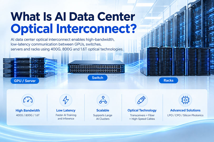
AI data centers rely heavily on high-speed interconnects between GPUs, NICs, switches and other computing resources. PAM4 enables higher lane rates that support 400G, 800G and emerging 1.6T network interfaces.
These interfaces are used in leaf-spine networks, GPU clusters, storage networks and data center interconnection.
33. PAM4 in GPU Networking
Large GPU clusters generate significant east-west traffic. High-speed PAM4 interfaces allow network devices to provide greater bandwidth per lane and increase the aggregate capacity of GPU fabrics.
Optical transceivers, DACs, AOCs and AECs can all use high-speed PAM4 signaling depending on the application and hardware architecture.
34. PAM4 and Fiber Reach
PAM4 itself does not determine optical transmission distance. Reach depends on the complete system, including optical source, receiver, fiber, wavelength, link budget, dispersion, FEC and module architecture.
This is why 400G SR4, DR4, FR4 and LR4 can all use PAM4 while providing different transmission distances.
35. PAM4 and BER Performance
BER is an important measurement for PAM4 systems. A lower BER indicates fewer bit errors in the received data.
Testing can include stressed conditions, different temperatures, varying received optical power and different electrical channel characteristics to determine the operating margin of the system.
36. PAM4 Testing
Common PAM4 test parameters include:
Eye height
Eye width
Eye symmetry
Jitter
Signal-to-noise ratio
Level separation
Transmitter output
Receiver sensitivity
Pre-FEC BER
Post-FEC BER
37. PAM4 Test Equipment
High-speed PAM4 testing can require equipment such as bit error rate testers, sampling oscilloscopes, real-time oscilloscopes, optical power meters and variable optical attenuators.
Testing should reproduce the electrical and optical conditions expected during actual deployment whenever possible.
38. PAM4 Design Challenges
The primary challenge of PAM4 is maintaining sufficient signal margin while operating at high data rates. Smaller eye openings increase sensitivity to noise, jitter, crosstalk and channel loss.
System designers therefore need to optimize the transmitter, electrical channel, optical components, receiver, equalization and FEC together.
39. Why PAM4 Is Important for 800G and 1.6T
Increasing aggregate bandwidth can be achieved through more lanes, higher lane rates or a combination of both. PAM4 enables higher bit rates without requiring a proportional increase in symbol rate.
This makes it an important technology for scaling high-speed Ethernet and optical interconnects as networks move from 400G toward 800G and 1.6T.
40. PAM4 and Future High-Speed Networking
As network speeds continue to increase, PAM4 remains an important signaling technology for optical and electrical interconnects. Higher lane rates will require continued improvements in semiconductor processes, equalization, packaging, optical devices, FEC and system-level signal integrity.
Future architectures may combine PAM4 with new optical technologies, linear-drive designs, co-packaged optics and other approaches to improve bandwidth density and energy efficiency.
41. Conclusion
PAM4 works by using four signal amplitude levels to encode two bits per symbol. Compared with NRZ, this increases the amount of information transmitted per symbol and enables higher data rates at manageable symbol rates.
The trade-off is reduced signal margin and greater sensitivity to noise, jitter, crosstalk and channel impairments. For this reason, PAM4 systems rely heavily on signal integrity, equalization, FEC and careful optical and electrical design.
Today, PAM4 is a fundamental signaling technology for high-speed networking, supporting applications across 100G, 200G, 400G, 800G and emerging 1.6T optical and electrical interconnects.
42. Frequently Asked Questions
Q1. What does PAM4 stand for?
Q2. How many bits does PAM4 carry per symbol?
Q3. What is the difference between PAM4 and NRZ?
Q4. Why does PAM4 have three eyes?
Q5. Why is PAM4 more sensitive to noise?
Q6. Is PAM4 used in 400G and 800G optical transceivers?
Q7. Does PAM4 determine the transmission distance?
Q8. What is the relationship between PAM4 and FEC?
Q9. Is PAM4 the same as LPO?
Q10. Why is PAM4 important for AI data centers?
43. Summary
PAM4 uses four amplitude levels to transmit two bits per symbol, enabling higher data rates without proportionally increasing the symbol rate. Its three-eye structure and reduced signal margin require careful control of noise, jitter, crosstalk, channel loss and receiver thresholds. PAM4 is now widely used in high-speed networking and optical interconnects, particularly for 400G, 800G and emerging 1.6T systems.
 >
>

 >
>
 >
>
 >
>
 >
>
 >
>
 >
>
 >
>