 TEL:+86 132 6656 7067





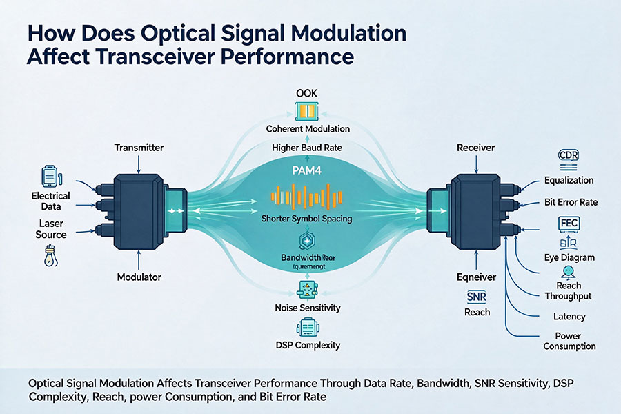
Optical transceiver performance depends not only on laser output power, receiver sensitivity and fiber quality, but also on how information is encoded onto the optical signal. The modulation format determines how much information each transmitted symbol carries, how clearly the receiver can distinguish signal states and how much processing is required to recover the original data.
In modern data center networks, NRZ and PAM4 are widely used intensity-modulation formats. As transmission rates increase, PAM4 allows more bits to be carried per symbol, helping optical interfaces achieve higher bandwidth without requiring an equivalent increase in symbol rate. In coherent optical systems, phase and amplitude modulation formats such as QPSK and 16QAM provide additional ways to increase spectral efficiency over longer distances.
However, higher modulation efficiency introduces different signal-quality requirements. The number of signal states, their separation, optical noise, dispersion tolerance and receiver architecture all influence the achievable bit error rate, transmission distance and power consumption.
1. What Is Optical Signal Modulation?
Optical signal modulation is the process of encoding digital information onto a light wave by changing one or more of its properties. The transmitter uses a laser and, depending on the architecture, a modulation device to generate optical signals representing the data stream.
The receiver detects these changes and converts them back into electrical information. The modulation format determines which optical characteristics carry the information and how the receiver interprets them.
Optical communication systems use several modulation dimensions:
Intensity modulation: Information is represented by changes in optical power or amplitude.
Phase modulation: Information is encoded through changes in the phase of the optical carrier.
Frequency modulation: Information is represented through changes in optical frequency.
Polarization-based modulation: Information can be carried through different polarization states.
Direct-detection optical transceivers commonly use intensity-based formats such as NRZ and PAM4. Coherent optical transceivers can detect both amplitude and phase information, enabling more advanced modulation formats and higher spectral efficiency.
2. How NRZ Modulation Affects Optical Transceiver Performance
Non-Return-to-Zero (NRZ) is a two-level modulation format in which the optical signal represents digital information using two distinct states. In a simplified intensity-modulation system, one level represents binary 0 and the other represents binary 1.
Each symbol carries one bit of information. Therefore, the bit rate and symbol rate are numerically equal when expressed in their respective units, before considering coding and interface overhead.
1 symbol = 1 bit
Bit Rate = Symbol Rate
NRZ has a relatively simple signal structure. Its two amplitude levels provide greater separation than a four-level signal under comparable normalized amplitude conditions, which can make receiver discrimination less demanding.
Its main limitations become apparent as the required data rate increases. To achieve higher bandwidth, the transmitter must increase the symbol rate, placing greater demands on laser modulation bandwidth, receiver bandwidth and the electrical channel.
| Performance Factor | NRZ Characteristics | Engineering Impact |
|---|---|---|
| Bits per symbol | 1 | Requires a higher symbol rate for a given bit rate than PAM4 |
| Signal levels | 2 | Relatively straightforward amplitude detection |
| Receiver requirements | Comparatively simple signal discrimination | Lower modulation complexity in many direct-detection designs |
| High-speed scaling | Requires increasing symbol rate | Greater bandwidth demand on optical and electrical components |
| Typical applications | Lower-rate optical interfaces and legacy systems | Still relevant where its performance and cost characteristics are appropriate |
NRZ remains useful in applications where the required data rate, reach, component cost and system architecture make it a suitable choice. However, it becomes less efficient for many modern high-speed interfaces that need to deliver substantially more data per optical lane.
3. How PAM4 Modulation Increases Optical Bandwidth
Pulse Amplitude Modulation with four levels (PAM4) represents data using four distinct signal amplitudes. Instead of carrying one bit per symbol, each PAM4 symbol represents a two-bit combination.
The four amplitude levels can be mapped to binary combinations such as 00, 01, 11 and 10. This allows PAM4 to carry twice as many bits per symbol as NRZ.
1 symbol = 2 bits
Bit Rate = Symbol Rate × 2
For example, a PAM4 signal operating at approximately 53.125 GBd carries approximately 106.25 Gbps of raw bit rate per lane. An NRZ signal would require approximately twice that symbol rate to carry the same raw bit rate.
| Parameter | NRZ | PAM4 |
|---|---|---|
| Number of signal levels | 2 | 4 |
| Bits per symbol | 1 | 2 |
| Symbol rate for 100 Gbps raw bit rate | 100 GBd | 50 GBd |
| Amplitude decision regions | 1 decision threshold | 3 decision thresholds |
| Signal-level spacing | Greater under comparable normalized amplitude conditions | Smaller |
| Signal processing requirements | Relatively simpler | More demanding equalization and signal-quality control |
The main advantage of PAM4 is bandwidth efficiency. It can increase the bit rate without requiring the same proportional increase in symbol rate, making it suitable for 100G-class optical lanes and higher-capacity interfaces.
The trade-off is that four signal levels must fit within a similar overall amplitude range. The separation between adjacent levels is therefore smaller, making the signal more vulnerable to noise, distortion, crosstalk and nonlinear effects.
4. Signal-Level Separation and Receiver Sensitivity
One of the most important differences between NRZ and PAM4 is the distance between signal levels. The receiver must distinguish each transmitted state from the others, even when the signal has been weakened or distorted during transmission.
In an NRZ system, the receiver makes a decision between two primary amplitude states. PAM4 requires the receiver to distinguish among four states using three decision thresholds.
When noise or distortion moves a received signal closer to a decision boundary, the probability of an incorrect symbol decision increases. This makes PAM4 more demanding in terms of signal-to-noise ratio and receiver performance.
Several factors influence the available receiver margin:
Optical receiver noise and photodetector performance.
Transimpedance amplifier bandwidth and noise characteristics.
Optical input power and receiver sensitivity.
Signal distortion and inter-symbol interference.
Jitter and timing recovery performance.
Equalization and digital signal processing capability.
Receiver sensitivity must therefore be evaluated together with the modulation format and the specified BER target. A sensitivity value measured under one modulation scheme or test condition cannot automatically be applied to another.
5. How Modulation Format Influences Transmission Distance
Transmission distance depends on the complete optical link budget and signal-quality margin. Modulation format is one factor because it affects how much noise and distortion the receiver can tolerate before the error rate becomes unacceptable.
For a given bit rate and comparable optical conditions, PAM4 generally requires more careful signal-quality management than NRZ because its amplitude levels are more closely spaced. This can reduce available implementation margin if the transmitter, receiver and optical channel are not designed accordingly.
However, it would be incorrect to conclude that PAM4 always has a shorter reach than NRZ. Actual transmission distance depends on the optical components, fiber type, wavelength, modulation bandwidth, receiver architecture, FEC and applicable interface specification.
| Link Factor | Potential Influence on Modulated Signals |
|---|---|
| Fiber attenuation | Reduces received optical power and available link margin |
| Chromatic dispersion | Can distort pulse shape and increase inter-symbol interference |
| Modal dispersion | Can spread signal energy across time in multimode fiber |
| Connector and splice loss | Reduces the optical power reaching the receiver |
| Optical noise | Reduces the receiver's ability to distinguish signal states |
| Receiver bandwidth | Limits how accurately high-speed signal transitions can be recovered |
| FEC capability | Determines how much residual bit error activity can be corrected |
In short-reach data center links, PAM4 supports higher lane rates within practical component bandwidth limits. For longer distances, coherent systems may use more advanced modulation and detection techniques to balance spectral efficiency, optical power and transmission performance.
6. The Role of QPSK and 16QAM in Coherent Optical Transceivers
NRZ and PAM4 are commonly associated with intensity-modulation direct-detection systems. Coherent optical transceivers use a different approach: they recover both amplitude and phase information from the received optical carrier.
This enables modulation formats such as Quadrature Phase Shift Keying (QPSK) and 16-state Quadrature Amplitude Modulation (16QAM).
QPSK uses four phase states. Each symbol carries two bits of information. 16QAM uses sixteen combinations of amplitude and phase, allowing each symbol to carry four bits.
| Modulation Format | Signal States | Bits per Symbol | Typical Context |
|---|---|---|---|
| NRZ | 2 amplitude levels | 1 | Direct-detection optical interfaces |
| PAM4 | 4 amplitude levels | 2 | High-speed data center optical interfaces |
| QPSK | 4 phase states | 2 | Coherent optical transmission |
| 16QAM | 16 amplitude and phase combinations | 4 | Higher spectral-efficiency coherent systems |
Higher-order coherent modulation can increase the amount of information transmitted within a given symbol rate. However, the signal states become more closely spaced in the combined amplitude-and-phase constellation, increasing the required signal-to-noise ratio.
QPSK is generally more tolerant of noise than 16QAM at comparable operating conditions, while 16QAM offers higher spectral efficiency when sufficient optical signal quality is available.
Coherent receivers use local oscillators, optical hybrids and high-speed digital signal processing to recover the transmitted information. They can also compensate for certain channel impairments, including chromatic dispersion and polarization-related effects.
7. How Modulation Affects Optical Power Requirements
Optical power requirements are closely related to modulation format, receiver sensitivity and the required BER performance. A modulation scheme with more closely spaced signal states generally needs better signal quality to achieve the same error performance under comparable conditions.
For PAM4, optical modulation amplitude (OMA) is an important transmitter measurement. OMA describes the optical power difference between defined signal levels and is useful for evaluating the strength of the modulated signal.
Extinction ratio is another relevant parameter. It describes the relationship between optical power levels and helps characterize the modulation quality of intensity-based transmitters.
In practical system design, engineers must consider:
Average optical launch power.
Optical modulation amplitude.
Extinction ratio.
Receiver sensitivity under the specified BER condition.
Receiver overload limit.
Optical channel loss and power margin.
Increasing average optical power alone does not necessarily solve modulation-related signal-quality problems. A distorted PAM4 eye diagram, for example, may remain problematic even when the received optical power is sufficient.
8. Modulation, BER and Forward Error Correction
Bit Error Rate (BER) measures the proportion of received bits that are incorrect. It is one of the main indicators used to evaluate optical link performance.
BER = Number of Erroneous Bits / Total Number of Received Bits
Because PAM4 has four signal levels and smaller decision margins, it requires careful control of transmitter linearity, receiver noise, timing and signal distortion. Error performance is commonly evaluated using pre-FEC and post-FEC measurements.
Forward Error Correction adds structured redundancy to the transmitted data. The receiver uses this information to identify and correct a limited number of errors.
FEC is particularly important in many high-speed PAM4 interfaces because it helps maintain the required end-to-end error performance despite a higher raw error rate before correction.
FEC can correct errors within the capability of the selected coding scheme. It cannot compensate indefinitely for inadequate optical power, severe waveform distortion, damaged fiber or excessive noise. The required FEC mode must also be supported by both ends of the link.
When evaluating modulation performance, engineers should check the pre-FEC BER, corrected error statistics and post-FEC error performance rather than relying on a single link-status indicator.
9. Eye Diagrams and TDECQ for Modulation Quality
An eye diagram provides a visual representation of signal quality by overlaying many signal transitions. It helps engineers assess amplitude margin, timing margin, jitter and inter-symbol interference.
An NRZ eye diagram contains one primary eye opening. PAM4 produces three eye openings because the receiver must distinguish among four amplitude levels.
Each PAM4 eye must maintain sufficient vertical and horizontal margin for reliable signal recovery. Noise, transmitter distortion, bandwidth limitations and timing errors can reduce these openings.
Transmitter and Dispersion Eye Closure Quaternary (TDECQ) is an important PAM4 transmitter performance metric in defined optical interface test procedures. It evaluates the transmitter's signal quality while accounting for specified filtering and dispersion-related conditions.
Other useful measurements include:
OMA: Evaluates the optical modulation amplitude.
Extinction ratio: Characterizes the relationship between optical signal levels.
TDECQ: Evaluates PAM4 transmitter quality under defined test conditions.
Jitter: Measures timing variation in the signal.
BER: Quantifies bit-level transmission errors.
Receiver sensitivity: Measures the minimum received signal level required to achieve a specified error performance.
These metrics must be interpreted according to the relevant standard, measurement reference point and test setup. TDECQ, for example, is not a universal performance metric for every NRZ or coherent optical interface.
10. How Modulation Affects Power Consumption and Thermal Performance
Modulation format can influence transceiver power consumption because different signal architectures require different transmitter, receiver and processing capabilities.
PAM4 systems may require more sophisticated driver linearity, receiver equalization and DSP processing than simpler NRZ implementations. These functions can increase circuit complexity and contribute to module power consumption.
Coherent optical modules typically require additional optical and electronic functions, including local oscillators, coherent detection and substantial digital signal processing. Their power requirements depend on the supported data rate, modulation format, reach and implementation.
Thermal management is therefore closely connected to modulation architecture. High-speed modules must maintain stable operating temperatures so that their lasers, drivers, receivers and processing circuits remain within specified performance limits.
For high-density 400G, 800G and 1.6T deployments, engineers should evaluate modulation format alongside module power consumption, host cooling capacity, airflow and port density.
11. Choosing the Right Modulation Format for Different Applications
No single modulation format is ideal for every optical network. The appropriate choice depends on the required data rate, transmission distance, available optical power, fiber infrastructure, receiver complexity and system cost.
| Application | Common Modulation Approach | Primary Design Consideration |
|---|---|---|
| Legacy and lower-rate optical links | NRZ | Cost, simplicity and required reach |
| 400G data center links | PAM4 | High lane bandwidth and signal integrity |
| 800G data center links | PAM4 | Higher electrical and optical lane rates |
| 1.6T optical interconnects | Higher-speed PAM4 implementations | Electrical bandwidth, optical performance and thermal design |
| Coherent metro and long-haul systems | QPSK, 16QAM and other coherent formats | Reach, spectral efficiency and optical signal-to-noise ratio |
These are common application patterns rather than exclusive rules. Actual modulation formats are defined by the applicable optical interface and product implementation.
12. C-LIGHT 400G OSFP and PAM4 Optical Transmission
PAM4 has become an important technology for high-bandwidth data center optical interfaces because it allows more information to be transmitted per symbol. The C-LIGHT 400G OSFP family provides a practical example of this approach.
The C-LIGHT 400G OSFP optical transceiver family supports 400Gbps connectivity for AI data centers, cloud computing and high-performance computing networks.
The product information describes high-speed electrical channel architectures using configurations such as 8 × 50G PAM4 or 4 × 100G PAM4, depending on the implementation.
Available optical configurations include:
400G SR4: 850 nm multimode optical transmission, with a listed reach of 100 m.
400G DR4: Single-mode parallel optical transmission, with a listed reach of 500 m.
400G FR4: LAN-WDM optical transmission, with a listed reach of 2 km.
400G LR4: LAN-WDM optical transmission, with a listed reach of 10 km.
The product family uses PAM4-based high-speed signaling and supports OSFP-based data center applications. The exact modulation mapping, electrical interface and optical performance specifications should be confirmed against the datasheet for the selected part number.
For network designers, the key consideration is not simply whether a module supports PAM4. Its optical reach, receiver sensitivity, FEC requirements, lane configuration and host compatibility must also meet the target application.
13. Conclusion
Optical signal modulation has a direct influence on transceiver bandwidth, receiver sensitivity, BER, transmission distance and power consumption. NRZ provides a relatively simple two-level signal structure, while PAM4 carries two bits per symbol and supports higher data rates within a lower symbol-rate requirement.
The increased bandwidth efficiency of PAM4 comes with tighter signal-quality requirements. Its smaller amplitude-level spacing makes transmitter linearity, receiver sensitivity, equalization, TDECQ and FEC increasingly important. In coherent optical systems, QPSK and 16QAM extend modulation capabilities by using phase and amplitude information to improve spectral efficiency.
Choosing the right modulation format requires a complete view of the optical link, including the transmitter, fiber channel, receiver, signal-processing architecture and target transmission distance. As 400G, 800G and 1.6T networks continue to evolve, modulation technology remains a central factor in achieving reliable, high-capacity optical connectivity.
C-LIGHT provides optical transceiver solutions for 400G, 800G and next-generation data center networks. For assistance with modulation formats, optical reach, host compatibility or product specifications, Contact C-LIGHT.
 >

 >
 >
 >
 >
 >
 >
 >














