TEL:+86 132 6656 7067




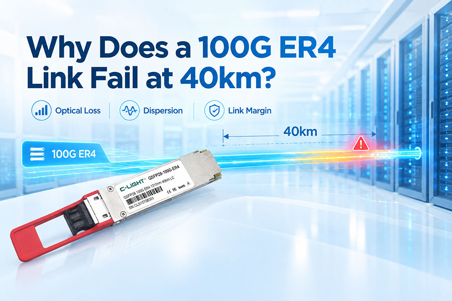
100G ER4 is a long-reach 100Gbps optical transceiver designed for transmission distances of up to 40km over single-mode fiber. It achieves this reach through four LAN-WDM wavelengths, high-performance optical transmitters and receivers, forward error correction support in the host system where applicable, and sufficient optical link budget.
1. What Is 100G ER4?
100G ER4 is a 100Gbps Ethernet optical transceiver typically implemented in the QSFP28 form factor. It is designed for extended-reach connections over single-mode fiber, with a typical maximum transmission distance of 40km.
Unlike short-reach 100G modules such as SR4, which use multimode fiber, 100G ER4 is optimized for long-distance single-mode fiber links.
2. Why Can 100G ER4 Reach 40km?
The 40km transmission distance is achieved through a combination of wavelength division multiplexing, high-quality optical components, receiver sensitivity, transmitter output power, and link-loss management.
The main factors include:
Four optical wavelengths around the 1310nm window
Single-mode fiber with low transmission loss
EML-based optical transmitters
High-sensitivity PIN receivers
Forward Error Correction support in the overall Ethernet system where required
A sufficiently large optical power budget
3. How Does the Four-Wavelength Architecture Work?
A typical 100G ER4 transceiver divides the 100Gbps electrical data into four optical lanes. Each lane operates at approximately 25Gbps and uses a different wavelength in the LAN-WDM band.
| Lane | Typical Wavelength | Data Rate |
|---|---|---|
| Lane 1 | ~1295nm | 25Gbps |
| Lane 2 | ~1300nm | 25Gbps |
| Lane 3 | ~1305nm | 25Gbps |
| Lane 4 | ~1310nm | 25Gbps |
The four wavelengths are multiplexed onto a single pair of single-mode fibers. At the receiving end, the optical signals are demultiplexed and converted back into electrical data.
4. Why Is the 1310nm Window Used?
The 1310nm wavelength region is widely used for single-mode fiber communication because fiber attenuation is relatively low and chromatic dispersion is well controlled compared with some other wavelength regions.
This makes the 1310nm window suitable for 100G long-reach Ethernet applications without requiring the more complex dispersion-management approaches associated with some longer-wavelength systems.
5. What Optical Transmitter Does 100G ER4 Use?
100G ER4 commonly uses directly modulated or externally modulated laser technologies depending on the specific implementation. High-performance ER4 designs often use EML technology to provide stable optical performance over the required transmission distance.
The transmitter must provide sufficient optical output power while maintaining signal quality across all four wavelengths.
6. What Role Does the Receiver Play?
The receiver converts the four optical signals back into electrical signals. PIN photodiodes are commonly used in 100G ER4 designs because they provide the required sensitivity and bandwidth for the application.
Receiver sensitivity is especially important for 40km links because optical power decreases as the signal travels through the fiber and passes through connectors and other passive components.
7. What Is the Optical Power Budget?
The optical power budget represents the difference between the transmitter launch power and the minimum receiver input power required for reliable operation.
For a 40km link, the available power budget must cover:
Fiber attenuation
Connector insertion loss
Splice loss
Component and MUX/DEMUX loss where applicable
Additional engineering margin
The longer the link, the more important the optical budget becomes.
8. How Much Loss Does 40km of Fiber Introduce?
Single-mode fiber around the 1310nm region typically has relatively low attenuation. However, a 40km link still introduces significant optical loss.
A simplified link-loss calculation can be represented as:
Total Loss = Fiber Loss + Connector Loss + Splice Loss + Other Passive Losses
For example, using an illustrative fiber attenuation of 0.35dB/km, 40km of fiber would contribute about 14dB of fiber loss before connectors and other passive losses are included.
9. Why Is Single-Mode Fiber Required?
100G ER4 is designed for single-mode fiber because long-distance transmission requires low attenuation and controlled optical propagation over tens of kilometers.
Multimode fiber is normally used for much shorter data center connections and is not the appropriate medium for a 40km ER4 link.
10. How Does LAN-WDM Help 100G ER4?
LAN-WDM allows four closely spaced wavelengths to carry separate 25Gbps optical signals over the same fiber pair.
This provides 100Gbps aggregate bandwidth without requiring four independent fiber pairs. The wavelength range also remains centered around the 1310nm region, making it suitable for long-reach single-mode fiber transmission.
11. How Does the Optical Signal Travel Through the Link?
The basic transmission process is:
100G Electrical Data → 4 × 25G Electrical Lanes → 4 LAN-WDM Optical Signals → WDM Multiplexing → 40km SMF → WDM Demultiplexing → Optical Detection → 100G Electrical Data
This architecture allows four optical channels to share the same fiber path while maintaining a 100Gbps aggregate data rate.
12. What Is the Role of FEC?
Forward Error Correction can improve the ability of the overall Ethernet link to tolerate transmission errors by adding redundant information to the data stream.
For long-reach 100G applications, FEC can provide additional margin against optical impairments. Whether FEC is required depends on the specific Ethernet standard, transceiver implementation, and host equipment.
13. How Does Chromatic Dispersion Affect 100G ER4?
Chromatic dispersion causes different optical components of a signal to travel at slightly different speeds through the fiber. Over long distances, this can broaden the signal and reduce the available system margin.
Operating around 1310nm helps control chromatic-dispersion effects for standard single-mode fiber, which is one reason the wavelength region is widely used for 100G ER4.
14. Why Is ER4 Different From 100G SR4?
| Feature | 100G SR4 | 100G ER4 |
|---|---|---|
| Fiber | MMF | SMF |
| Typical wavelength | 850nm | LAN-WDM around 1310nm |
| Reach | Short reach | Up to 40km |
| Typical application | Data center | Data center and metro links |
15. Why Does ER4 Need More Optical Power Than Short-Reach Modules?
A short-reach module may only need to overcome a few meters of fiber and limited connector losses. A 40km ER4 link must compensate for much greater fiber attenuation and additional passive losses.
As a result, ER4 designs typically require a stronger transmitter and a more sensitive receiver than short-reach optical modules.
16. What Components Affect 40km Transmission Performance?
Several optical components directly influence the achievable distance:
Laser output power
Laser wavelength accuracy
Optical modulation quality
Receiver sensitivity
Fiber attenuation
Connector insertion loss
Splice loss
WDM optical loss
System FEC performance
17. How Important Is Connector Loss?
Although each connector introduces only a small amount of insertion loss, several connectors can reduce the total optical margin of a 40km link.
This is why long-distance links should use clean, high-quality connectors and well-managed patching systems.
18. Can 100G ER4 Really Transmit 40km?
Yes. 100G ER4 is specifically designed for extended-reach 100Gbps transmission over single-mode fiber, with 40km being a common target reach for ER4-class solutions.
The actual achievable distance depends on the transceiver optical budget, fiber characteristics, connector and splice losses, and the complete network design.
19. What Happens When the Link Loss Is Too High?
If total link loss exceeds the available optical power budget, the receiver may not receive a sufficiently strong signal. This can lead to higher bit error rates, unstable links, or complete link failure.
For this reason, a 40km installation should always be evaluated using an actual link-loss budget rather than distance alone.
20. How Should a 100G ER4 Link Be Designed?
A practical 40km deployment should consider the complete optical path rather than simply selecting a 40km transceiver.
The design should include fiber length, fiber attenuation, connector count, splice count, patch panels, optical distribution equipment, and an appropriate system margin.
21. What Applications Use 100G ER4?
100G ER4 can be used in applications where 100Gbps connectivity must extend beyond typical data center distances, including:
Metro data center interconnection
Campus network backbone links
Enterprise aggregation networks
Telecommunications infrastructure
Long-distance Ethernet connections
Data center interconnect applications
22. Can 100G ER4 Be Used for Data Center Interconnect?
Yes. Its combination of 100Gbps capacity and up to 40km reach makes ER4 suitable for connecting facilities, aggregation sites, or network locations separated by significant distances.
23. What Form Factor Is Commonly Used for 100G ER4?
QSFP28 is one of the most common form factors for 100G ER4 optical transceivers. It provides a compact 100G solution with broad compatibility across Ethernet switching and routing platforms.
24. What Connector Does 100G ER4 Usually Use?
100G ER4 commonly uses duplex LC connectors because the architecture uses one fiber for transmit and one fiber for receive.
This differs from parallel-optics modules such as SR4, which commonly use MPO connectors.
25. 100G ER4 vs Other 100G Long-Reach Solutions
| Solution | Typical Fiber | Typical Reach | Main Characteristic |
|---|---|---|---|
| 100G SR4 | MMF | Short reach | Low-cost short-distance connectivity |
| 100G DR | SMF | Up to about 500m | Single-mode data center interconnect |
| 100G FR4 | SMF | Up to about 2km | Four-wavelength LAN-WDM |
| 100G ER4 | SMF | Up to about 40km | Extended-reach Ethernet |
26. What Are the Main Advantages of 100G ER4?
The main advantages of 100G ER4 are its 100Gbps capacity, long transmission distance, single-mode fiber support, duplex LC connectivity, and compatibility with extended-reach Ethernet applications.
27. What Are the Limitations of 100G ER4?
100G ER4 is more complex and generally more expensive than short-reach 100G solutions. Its optical components must meet tighter performance requirements, and long-distance deployments require careful link-budget planning.
28. How Does 100G ER4 Achieve 40km Transmission?
100G ER4 achieves 40km transmission through the combination of four LAN-WDM wavelengths, high-performance optical transmitters and receivers, low-loss single-mode fiber, adequate optical power budget, and appropriate system error-control techniques.
The 40km reach is therefore not the result of a single component. It is the result of coordinated optical design across the transmitter, fiber, receiver, connectors, and host networking system.
29. FAQ
Q1. What is 100G ER4?
Q2. How does 100G ER4 reach 40km?
Q3. What fiber does 100G ER4 use?
Q4. What connector does 100G ER4 use?
Q5. Is FEC required for 100G ER4?
Q6. Is 40km the actual distance of every 100G ER4 link?
30. Summary
100G ER4 achieves up to 40km transmission by combining four LAN-WDM optical wavelengths in the 1310nm region with high-performance transmitters and receivers and low-loss single-mode fiber. Proper optical power budgeting and system design are equally important for maintaining reliable 100Gbps communication over long distances.
 >
>

 >
>
 >
>
 >
>
 >
>
 >
>
 >
>
 >
>