TEL:+86 132 6656 7067





As data center networks advance from 100G and 400G to 800G and 1.6T, optical transceiver power consumption has become an important factor in network infrastructure design. Higher bandwidth per port improves switching capacity and reduces the number of physical connections required, but faster optical interfaces also introduce greater demands on electrical signal processing, optical components, and thermal management.
For network operators, the challenge is not simply reducing the power consumption of an individual module. It is balancing bandwidth, transmission distance, optical performance, port density, cooling capacity, and total system energy consumption. Understanding power consumption at both the module and network levels is essential for building efficient high-speed optical infrastructure.
1. Why Optical Transceiver Power Consumption Matters
Optical transceivers are installed across server connections, leaf-spine networks, data center interconnects, and telecommunications systems. In high-density switches, dozens of optical modules may operate simultaneously. Their combined power consumption can represent a significant portion of the equipment's total energy demand.
Power consumption affects several aspects of network engineering:
Equipment power budget: Each module draws electrical power from the host device, contributing to the total switch or router load.
Cooling requirements: Electrical power consumed by a module is converted largely into heat that must be removed from the system.
Port density: High-power modules can impose limits on how many ports can operate simultaneously within a chassis.
Operating efficiency: Lower energy consumption per transmitted bit can improve the efficiency of high-capacity networks.
Infrastructure planning: Optical power requirements influence power distribution, cooling design, and rack-level capacity planning.
These considerations become particularly important in AI data centers, where large numbers of 400G and 800G optical interfaces may operate continuously across GPU clusters and switching fabrics.
2. Main Sources of Optical Transceiver Power Consumption
The power consumption of an optical module depends on its optical architecture, electrical interface, data rate, transmission distance, and internal signal-processing requirements. Several components contribute to the total power budget.
Digital Signal Processor (DSP)
The DSP is one of the major power-consuming components in many modern high-speed optical transceivers. It performs functions such as signal equalization, clock recovery, modulation-related processing, and forward error correction support.
At 400G and 800G, high-speed electrical interfaces and PAM4 signaling require sophisticated signal processing. Depending on the architecture, DSP power can account for a substantial proportion of total module consumption.
Laser and Optical Transmitter
The optical transmitter converts electrical signals into light. Its power requirements depend on the laser technology, modulation method, optical output requirements, and transmission distance.
Different optical designs, including VCSEL, DFB, and EML-based implementations, have different operating characteristics. Long-reach and high-performance applications may require more complex optical components than short-reach multimode modules.
Driver and Receiver Electronics
Laser drivers control the optical transmitter, while photodetectors and transimpedance amplifiers (TIAs) convert received optical signals into electrical signals. These components contribute to the total electrical power budget and must maintain signal quality at the required data rate.
Thermal Electric Cooler (TEC)
Some optical modules use TEC devices to stabilize laser temperature and maintain wavelength performance. TEC operation can add power consumption, particularly in applications requiring precise wavelength control or stable operation across changing environmental conditions.
Control and Power Management Circuits
Microcontrollers, monitoring circuits, voltage regulators, and other supporting components also consume power. Their individual contribution may be smaller than that of the DSP or optical engine, but they remain part of the overall module power budget.
| Component | Main Function | Power Consideration |
|---|---|---|
| DSP | Signal processing, equalization and FEC-related functions. | Can be a major power contributor in high-speed modules. |
| Laser | Generates the optical signal. | Depends on laser technology and optical output requirements. |
| Driver | Controls the optical transmitter. | Depends on modulation and electrical signaling requirements. |
| Photodetector and TIA | Converts received light into electrical signals. | Depends on receiver sensitivity and bandwidth requirements. |
| TEC | Stabilizes optical component temperature. | May add power in temperature-controlled designs. |
| Control electronics | Monitoring, management and power regulation. | Additional supporting power consumption. |
3. Power Consumption Across 100G, 400G, 800G and 1.6T Modules
Higher data rates generally require more advanced electrical and optical architectures. As a result, the absolute power consumption of an individual module often increases with transmission capacity. However, power consumption does not necessarily increase in direct proportion to bandwidth.
The following figures are illustrative engineering ranges rather than universal limits. Actual power depends on the specific module model, optical reach, form factor, DSP implementation, temperature conditions, and manufacturer specifications.
| Data Rate | Example Module Type | Illustrative Power Range | Common Application |
|---|---|---|---|
| 100G | QSFP28 SR4 / LR4 | Approximately 2–5W | Enterprise and data center links. |
| 400G | QSFP-DD DR4 / FR4 | Approximately 8–12W | High-speed data center switching. |
| 800G | OSFP DR8 / 2FR4 | Approximately 13–18W | AI clusters and hyperscale networks. |
| 1.6T | OSFP DR8 / 2FR4 | Architecture-dependent; approximately 20–30W for some implementations. | Next-generation AI and high-density switching. |
These ranges should not be used as substitutes for product datasheets. For example, a short-reach 800G module and an 800G coherent module can have substantially different power requirements despite sharing the same nominal data rate.
Why Higher Data Rates Require More Power
Increasing bandwidth requires higher-speed electrical signaling, more optical channels, or more advanced modulation and signal processing. The implementation may involve additional DSP resources, faster laser drivers, more complex receivers, and tighter thermal requirements.
Transmission distance is another important factor. A short-reach multimode module may use a relatively simple optical architecture, while a long-distance coherent module requires more sophisticated digital processing and optical control.
4. Power Efficiency and Energy per Bit
Absolute power consumption alone does not provide a complete picture of optical module efficiency. A 16W module transmitting 800G may deliver more data per watt than an 8W module transmitting 400G.
Energy per bit provides a useful way to evaluate this relationship. It expresses the amount of energy required to transmit one bit of information.
Because one watt equals one joule per second and one terabit equals 1012 bits, dividing power in watts by data rate in terabits per second produces energy per bit in picojoules.
Example: Comparing 400G and 800G
| Module Example | Power | Data Rate | Energy per Bit |
|---|---|---|---|
| 400G optical module | 10W | 0.4 Tb/s | 25 pJ/bit |
| 800G optical module | 16W | 0.8 Tb/s | 20 pJ/bit |
| 1.6T optical module | 24W | 1.6 Tb/s | 15 pJ/bit |
In this simplified example, the 800G module consumes more absolute power than the 400G module, but its energy consumption per bit is lower. The 1.6T example improves the ratio further.
5. How Form Factor Influences Power and Thermal Design
Optical module form factors define mechanical dimensions, electrical interfaces, cooling arrangements, and supported power classes. They therefore influence the practical power envelope available to different optical architectures.
QSFP-DD
QSFP-DD supports high-density 400G and 800G optical connectivity. Its compact design makes it attractive for switch platforms requiring a high number of front-panel ports. However, higher-power implementations require careful host-side heatsink contact and airflow management.
OSFP
OSFP was designed for high-speed optical applications and provides a larger physical and thermal design envelope than QSFP-DD. Its integrated heatsink design supports demanding optical applications, including high-power 800G and emerging 1.6T modules.
OSFP-RHS
Reduced-height heatsink designs address specific system integration requirements. They are particularly relevant in high-density AI systems where optical modules may need to work alongside advanced cooling structures.
The form factor alone does not determine module power consumption. DSP architecture, optical reach, laser technology, and product implementation remain major factors.
| Form Factor | Common Data Rates | Design Considerations |
|---|---|---|
| QSFP28 | 100G | Established compact design for 100G applications. |
| QSFP-DD | 400G / 800G | High port density and platform-dependent thermal management. |
| OSFP | 400G / 800G / 1.6T | Designed for higher-speed interfaces and demanding thermal requirements. |
| OSFP-RHS | 800G / 1.6T implementations | Reduced-height heatsink structure for specialized system integration. |
6. Optical Technologies That Improve Power Efficiency
Several optical architectures aim to reduce the energy required for high-speed transmission. Their benefits depend on the network design, electrical interface, reach requirement, and system-level signal integrity.
Linear Pluggable Optics (LPO)
LPO removes the conventional DSP from the optical module and uses a more direct electrical signal path between the host ASIC and optical components. This can reduce module power consumption and latency.
However, removing module-level DSP transfers more responsibility to the host electrical interface. The switch ASIC, board design, and signal channel must provide sufficient signal integrity. LPO is therefore not a universal replacement for DSP-based modules.
Linear Receive Optics and Reduced-DSP Designs
Reduced-DSP architectures aim to simplify selected signal-processing functions while retaining the capabilities needed for reliable transmission. Depending on the implementation, they can provide a balance between power efficiency and signal-conditioning requirements.
Silicon Photonics
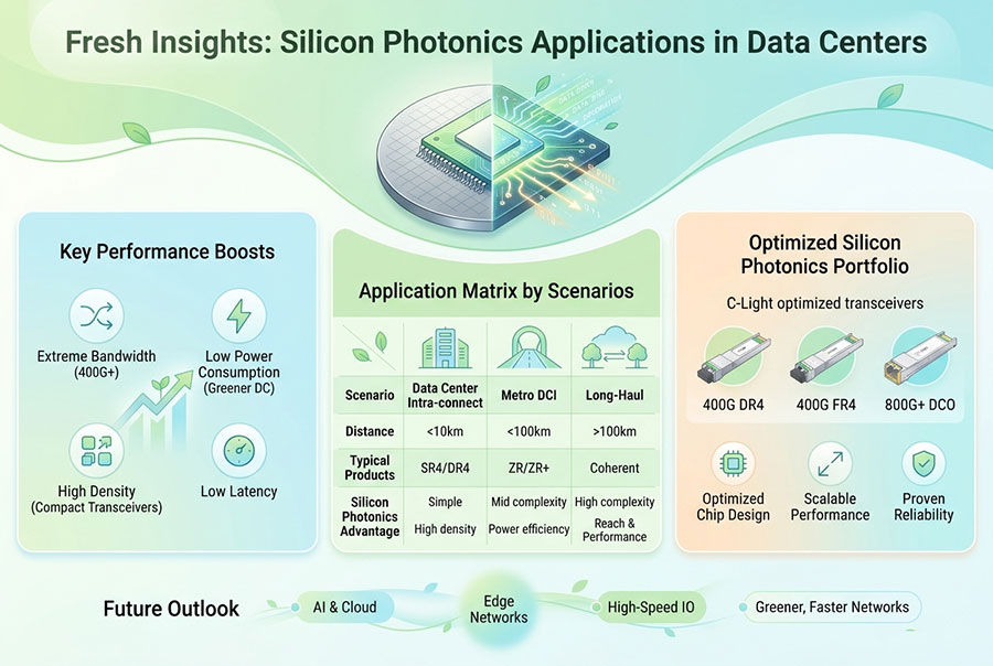
Silicon photonics integrates optical functions onto a semiconductor platform. It can support compact optical engines and advanced integration approaches. Its overall power efficiency depends on the laser architecture, modulation method, driver circuits, receiver design, and packaging.
Co-Packaged Optics (CPO)
CPO places optical engines closer to the switch ASIC, reducing the length of high-speed electrical connections. Shorter electrical paths can reduce signal-conditioning requirements and create opportunities for lower system power.
However, CPO also introduces challenges involving optical engine replacement, fiber management, packaging, thermal design, and serviceability. Its efficiency must be evaluated at the complete system level rather than by optical-engine power alone.
7. Thermal Management for High-Power Optical Modules
Power consumption and thermal management are closely connected. Most electrical energy consumed by an optical transceiver ultimately becomes heat, which must be transferred away from the module and host equipment.
Insufficient cooling can increase component temperatures, affect optical performance, and create reliability concerns. High-density 800G and 1.6T platforms therefore require careful thermal planning.
Airflow Management
Switch chassis airflow must be compatible with the module heatsink design. Engineers should consider airflow direction, fan capacity, adjacent module temperatures, and the thermal behavior of a fully populated front panel.
Heatsink and Mechanical Integration
The contact between the module and host cooling structure affects heat transfer. Mechanical tolerances, heatsink geometry, and the platform's thermal interface design all influence the actual operating temperature.
Liquid Cooling Compatibility
Some high-density AI systems use liquid cooling to manage thermal loads. Optical module packaging must be compatible with the surrounding cooling architecture. Specialized OSFP-RHS and other thermal-oriented designs may be considered where supported by the host system.
Temperature Monitoring
Digital monitoring functions can provide information about module temperature, supply voltage, laser bias, and optical power. These readings help engineers identify abnormal operating conditions and evaluate thermal performance during deployment.
8. Calculating Total Optical Power in a Data Center Switch
Individual module power may appear relatively small, but the total becomes significant when many ports are populated. A basic calculation can estimate the optical module power budget of a switch.
Example: 32-Port 400G Switch
Assume a switch has 32 active optical ports, with each 400G module consuming 10W.
The optical modules alone consume approximately 320W. This estimate does not include the switch ASIC, fans, power conversion losses, or other system components.
Example: 32-Port 800G Switch
If the same number of ports uses 800G modules consuming 16W each:
The total module power increases to approximately 512W. This illustrates why power distribution and thermal planning become increasingly important as network port speeds advance.
9. Practical Methods for Improving Optical Network Efficiency
Improving efficiency requires coordinated decisions across module selection, network architecture, and cooling infrastructure.
Select the appropriate optical reach: Avoid choosing a long-reach optical architecture when a supported short-reach solution meets the link requirements.
Evaluate energy per bit: Compare power consumption against actual aggregate bandwidth rather than considering watts alone.
Choose the correct form factor: Match QSFP-DD, OSFP, or OSFP-RHS modules to the host platform's mechanical and thermal requirements.
Review DSP and optical architecture: Consider conventional DSP, LPO, reduced-DSP, or other available designs according to system compatibility.
Optimize port utilization: Plan network capacity carefully to avoid unnecessary active interfaces and oversized switching configurations.
Improve cooling efficiency: Maintain suitable airflow, heatsink contact, temperature monitoring, and system-level thermal design.
Verify actual specifications: Use product datasheets and host platform documentation to confirm maximum power, operating temperature, and compatibility.
10. C-LIGHT High-Speed Optical Transceiver Solutions
C-LIGHT provides optical transceivers for data centers, AI computing networks, cloud infrastructure, and high-performance switching applications. Its portfolio includes 400G, 800G, and 1.6T solutions across different form factors and transmission architectures.
400G QSFP-DD Optical Transceiver
Designed for high-speed Ethernet and data center connectivity, the 400G QSFP-DD portfolio includes SR8, DR4, FR4, LR4, and coherent configurations. Different optical architectures have different power and thermal requirements.
800G QSFP-DD Optical Transceiver
Supporting high-bandwidth data center and AI network applications, the 800G QSFP-DD series includes optical configurations for different transmission distances and system requirements.
800G OSFP Optical Transceiver
The 800G OSFP series supports configurations including SR8, DR8, and 2FR4. These modules are designed for high-density switching, AI clusters, and hyperscale data center networks.
1.6T OSFP-RHS Optical Transceiver
The 1.6T OSFP-RHS platform is designed for next-generation AI and hyperscale data center infrastructure. Its reduced-height heatsink structure supports specialized thermal integration, including compatible cold-plate cooling environments.
For additional product categories and optical interface options, visit the C-LIGHT Optical Transceiver Portfolio.
When selecting a high-speed optical module, customers should evaluate the actual power specification of the required part number, rather than assuming that all modules within the same data-rate or form-factor category have identical consumption.
11. Conclusion
Optical transceiver power consumption is becoming an increasingly important consideration as data center networks move toward 400G, 800G, and 1.6T connectivity. Higher-speed modules can deliver more bandwidth per port, but their electrical processing, optical components, and thermal requirements create new challenges for network infrastructure.
Energy per bit provides a useful measure of transmission efficiency, while absolute power consumption remains essential for equipment power budgeting and cooling design. Technologies such as LPO, silicon photonics, reduced-DSP architectures, and co-packaged optics offer different approaches to improving efficiency, each with its own system-level requirements.
Successful deployment depends on selecting the right optical architecture, verifying product specifications, and coordinating module power with host platform and cooling capabilities. These factors will remain central to the development of efficient, high-density optical networks.
Find the Right High-Speed Optical Transceiver
Looking for 400G, 800G, or 1.6T optical modules for data center and AI network applications? Contact C-LIGHT for product specifications, power information, compatibility support, and customized optical connectivity solutions.
Contact C-LIGHT >

 >
 >
 >
 >
 >
 >
 >