TEL:+86 132 6656 7067





High-capacity optical networks increasingly depend on transceivers that deliver higher bandwidth, stronger optical performance, and reliable operation under demanding equipment conditions. As optical interfaces move toward 400G, 800G, and beyond, engineers must evaluate more than transmission distance and nominal data rate. Transmitter output power, receiver operating range, electrical power consumption, and thermal performance all influence the reliability of an optical link.
1. What Defines a High-Power Optical Transceiver?
The term high-power optical transceiver can refer to different characteristics depending on the application. In optical transmission engineering, it may describe a module with relatively high transmitter output power, an extended-reach coherent module, or a transceiver with higher electrical power consumption.
These characteristics are related to different parts of the system and should be evaluated separately. A module designed for long-distance coherent transmission may require advanced digital signal processing, tunable lasers, and additional electrical power. This does not necessarily mean that its optical transmitter emits an unusually high power level.
Optical Output Power
The optical signal level generated by the transmitter. It affects the available link budget and must remain within the receiver and line-system operating limits.
Electrical Power Consumption
The electrical power required by the module for its laser, DSP, drivers, receivers, control circuits, and other internal components.
Thermal Performance
The module's ability to maintain reliable operation within its specified case-temperature range and the host platform's cooling capability.
For high-speed applications, all three factors must be considered during transceiver selection. A module can satisfy the optical link budget but still be unsuitable for a switch with insufficient power delivery or cooling capacity.
2. Understanding Optical Transmit Power and dBm
Optical transmitter output power is normally measured in dBm, a logarithmic unit referenced to 1 milliwatt. It describes the power level launched by the transmitter into the optical interface under specified operating conditions.
| Optical Power | Approximate Linear Power | Engineering Interpretation |
|---|---|---|
| -10 dBm | 0.1 mW | Low optical output level |
| -5 dBm | 0.316 mW | Below 1 mW |
| 0 dBm | 1 mW | Reference optical power level |
| +3 dBm | Approximately 2 mW | Approximately twice the power of 0 dBm |
| +10 dBm | 10 mW | Ten times the power of 0 dBm |
A higher transmitter output level can help compensate for optical losses in certain link designs. However, increasing launch power is not a universal solution for transmission problems. Excessive optical power can exceed the receiver's maximum input specification or introduce additional nonlinear effects in some optical systems.
The correct transmitter power must therefore be evaluated together with fiber attenuation, passive component losses, amplification, receiver sensitivity, and receiver overload limits.
3. Optical Power Budget: The Foundation of Link Design
The optical power budget represents the difference between the transmitter's output power and the receiver's sensitivity under specified conditions. It indicates how much attenuation the link can tolerate before the received signal falls below the required operating threshold.
For example, assume a hypothetical optical module has a minimum transmit power of -2 dBm and a receiver sensitivity of -16 dBm.
This means the link has a nominal 14 dB power budget under the stated assumptions. Actual deployment must reserve an appropriate engineering margin and account for all optical path losses.
A practical link budget must include the losses introduced by the complete optical path, rather than considering fiber attenuation alone.
| Loss Component | Source of Loss | Design Consideration |
|---|---|---|
| Fiber attenuation | Optical signal attenuation along the fiber | Depends on fiber type, wavelength, and route length |
| Connector loss | Fiber connectors and mating interfaces | Connector condition and cleanliness influence loss |
| Splice loss | Fusion or mechanical splices | Depends on splice quality and fiber alignment |
| Mux/demux insertion loss | Wavelength multiplexers and demultiplexers | Must be included in DWDM and CWDM link calculations |
| Additional passive components | Splitters, filters, patch panels, and other optical elements | Use the specified insertion loss for each component |
| Engineering margin | Future degradation and measurement uncertainty | Reserve sufficient margin for stable operation |
The basic received-power calculation for an unamplified link is:
For a path containing optical amplifiers, the calculation must also include amplifier gain and associated noise characteristics. In coherent systems, received power alone is not sufficient to determine link quality; OSNR and other transmission parameters must also be evaluated.
4. Receiver Sensitivity and Receiver Overload
Receiver sensitivity and receiver overload define two important boundaries of the optical receiver's operating range.
Receiver sensitivity is the minimum optical input power at which the receiver can achieve the specified performance under defined conditions. Receiver overload is the maximum input level that the receiver can accept while maintaining its specified operation.
| Receiver Parameter | Meaning | Potential Impact |
|---|---|---|
| Receiver sensitivity | Minimum required received optical power | Insufficient power can cause degraded performance or link failure |
| Receiver overload | Maximum specified received optical power | Excessive input power can cause receiver performance degradation |
| Operating range | Specified range between receiver limits | Defines the acceptable received-power window |
| Optical margin | Reserved allowance within the link design | Helps accommodate expected variations and aging |
A common design mistake is to focus only on achieving sufficient received power. A short optical connection can produce a received signal level that is too high for a particular receiver, especially when a high-output transmitter is connected through a low-loss path.
For this reason, the expected received power should be checked against both the minimum and maximum receiver specifications. Where the system design requires attenuation, the appropriate optical attenuation components must be selected according to the equipment and optical interface requirements.
5. High Optical Power and Long-Distance Transmission
Long-distance optical transmission requires careful coordination between transmitter power, fiber characteristics, receiver performance, and optical amplification. Increasing launch power can improve the received signal level in some situations, but the relationship between launch power and transmission quality is not unlimited.
In single-mode fiber systems, high optical launch power can contribute to nonlinear transmission effects. These effects may become more significant depending on fiber type, channel configuration, optical power, wavelength, and transmission distance.
For DWDM systems, multiple wavelengths share the same fiber. The aggregate optical power and interaction between channels must be considered, especially when optical amplifiers are used.
Fiber Attenuation
Determines how much optical power is lost along the transmission route.
Optical Amplification
Compensates for accumulated loss, while also introducing amplified spontaneous emission noise.
Nonlinear Effects
Can limit transmission performance when optical power and fiber conditions create significant nonlinear interactions.
In coherent DWDM networks, optical signal-to-noise ratio (OSNR), modulation format, FEC performance, and spectral efficiency are important design parameters. A higher transmitter power setting does not necessarily produce a better end-to-end signal.
6. Electrical Power Consumption in High-Speed Optical Modules
Electrical power consumption is a separate consideration from optical output power. It represents the power drawn by the transceiver from the host equipment and is measured in watts.
As data rates increase, optical modules may require more advanced DSP, high-speed electrical interfaces, laser drivers, receivers, and control circuits. These components contribute to the module's total electrical power consumption.
| Module Subsystem | Primary Function | Power-Related Consideration |
|---|---|---|
| Laser and optical engine | Generates and modulates the optical signal | Operating current and optical architecture |
| DSP | Signal processing, equalization, and error correction functions | Can be a significant power consumer in high-speed modules |
| Driver and receiver circuits | Support high-speed electrical-to-optical and optical-to-electrical conversion | Depend on lane rate and circuit architecture |
| Control and monitoring | Manages module configuration and diagnostics | Includes microcontroller and monitoring circuitry |
| Power conversion | Provides internal operating voltages | Conversion efficiency affects total module power |
A module's total electrical power consumption contributes to the thermal load inside the switch or router. In a high-density system, the combined power consumption of many optical modules can become a substantial part of the equipment's overall cooling requirement.
For example, a 400G module specified at a maximum electrical power consumption of 23 W requires a host platform that can support its power demand and thermal operating conditions. The figure is an electrical consumption rating, not the optical output power.
7. Thermal Management and Optical Module Temperature
Almost all electrical power consumed by an optical transceiver ultimately becomes heat within the equipment environment. The module's temperature is influenced by its own power consumption, the surrounding air temperature, airflow, heatsink design, neighboring components, and the host chassis.
High module temperature can affect component operating conditions and may lead to reduced performance, alarms, or operation outside the specified temperature range.
Airflow
Consistent airflow helps transfer heat away from the module and prevent local temperature accumulation.
Heatsink Design
Thermal interfaces and heatsink structures help conduct heat from the module into the host cooling system.
Equipment Density
Closely spaced high-power modules increase the total thermal load and can create localized hot spots.
Thermal evaluation should consider the complete equipment environment rather than the module in isolation. A transceiver that operates correctly in a laboratory setup may encounter different thermal conditions when installed in a fully populated switch.
8. Case Temperature, Ambient Temperature, and Operating Limits
Optical transceiver specifications may define an operating case-temperature range. Case temperature refers to the temperature measured at a specified location on the module housing, not necessarily the surrounding room or rack temperature.
The distinction is important because internal module temperature can be higher than the ambient temperature around the equipment. Airflow restrictions, nearby heat sources, and chassis design can increase the module's case temperature.
| Temperature Parameter | Definition | Why It Matters |
|---|---|---|
| Ambient temperature | Temperature of the surrounding operating environment | Influences the cooling system's available thermal margin |
| Case temperature | Temperature measured at the specified module case location | Used to evaluate compliance with module operating limits |
| Internal component temperature | Temperature within the module's internal components | Can differ from case temperature due to internal heat generation |
| Storage temperature | Specified temperature range for non-operating storage | Does not represent the permitted operating range |
Engineers should use the module datasheet's specified measurement conditions and temperature limits. A room-temperature reading alone cannot confirm that a high-power module is operating within its permitted case-temperature range.
9. High-Power 400G Coherent Transceiver: A Practical Example
400G coherent optical transceivers illustrate why optical power and electrical power must be evaluated independently. These modules integrate coherent optical functions and digital signal processing into a compact pluggable form factor for high-capacity data center interconnect and transport applications.
One example is the C-LIGHT 400G ZR+ High-Power Coherent QSFP-DD transceiver, model CL400GQDDZR+HP.
The published product datasheet lists a maximum electrical power consumption of 23 W, a 0°C to 70°C operating case-temperature range, full C-band tunability, flexible-grid support, and an optical transmitter power feature specified at 0 dBm.
The product is designed for coherent 400G/200G/100G optical interfaces based on the ZR+ MSA and uses a duplex LC optical connector.
This example demonstrates two independent design requirements:
Optical design: The wavelength, optical output, OSNR tolerance, receiver characteristics, and line-system configuration must be suitable for the intended transmission path.
Thermal and electrical design: The host platform must support the module's maximum power requirement and maintain its case temperature within the specified operating range.
The 23 W figure should be used as the module's maximum electrical power specification, not as a measure of optical launch power. The actual optical link budget must be calculated from the relevant transmitter and receiver specifications in the product datasheet.
10. Liquid Cooling and High-Density Optical Connectivity
As AI clusters and high-performance computing systems increase rack power density, traditional air-cooling designs face greater thermal challenges. Liquid cooling technologies are being adopted in different data center architectures to improve heat removal from high-density computing equipment.
Optical connectivity must be considered as part of the overall cooling architecture. A module intended for conventional air-cooled equipment should not automatically be assumed suitable for direct deployment in an immersion environment.
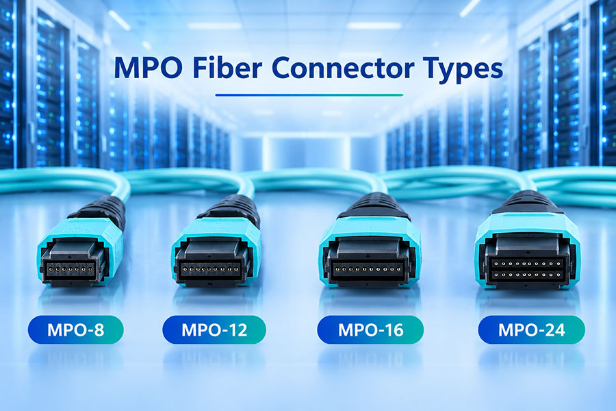
C-LIGHT lists liquid-immersion optical connectivity options designed for specific liquid-cooled computing environments. The published product table includes a 100G QSFP28-to-MPO configuration and a 25G/10G SFP28-to-UniBoot LC configuration, using 850nm multimode optics, OM3 fiber, and 0.8m connection lengths.
These configurations are intended for short-reach connectivity in compatible immersion-cooled environments. The listed product specifications should be checked against the actual cooling medium, mechanical installation, connector arrangement, and system requirements.
Liquid cooling does not remove the need for thermal validation. The module, connector, cable assembly, sealing structure, and cooling environment must all be suitable for the intended application. Product compatibility should be confirmed before deployment.
11. Common High-Power Transceiver Problems
High-power optical links can experience problems when optical and thermal specifications are not evaluated together. The following issues are particularly relevant in high-density network deployments.
| Problem | Possible Cause | Engineering Check |
|---|---|---|
| Receiver overload | Received optical power exceeds the receiver's maximum input specification | Measure RX power and compare it with the module's operating range |
| Insufficient received power | Excessive fiber, connector, or passive component loss | Measure end-to-end insertion loss and review the link budget |
| High module temperature | Restricted airflow or excessive equipment thermal load | Check case temperature, fan operation, and chassis airflow |
| Module power alarm | Host power limitation or module operating condition outside specification | Verify platform support and module power requirements |
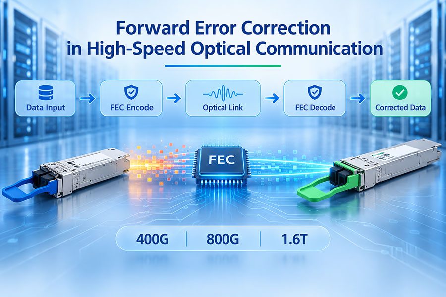
| Unstable high-speed link | Signal quality, optical margin, thermal, or compatibility issue | Review DOM data, error counters, FEC statistics, and host compatibility |
| Degraded coherent performance | Insufficient OSNR or unsuitable optical line-system conditions | Evaluate OSNR, channel configuration, and coherent link performance |
Digital optical monitoring can help identify abnormal operating conditions. Depending on the module, available parameters may include temperature, supply voltage, laser bias current, transmit power, and receive power. These readings should be interpreted alongside equipment alarms and link-performance statistics.
12. Selecting High-Power Optical Transceivers
The right module should be selected according to the complete network design. A high-power designation alone does not establish whether a transceiver is suitable for a specific switch, router, fiber route, or optical line system.
Data rate and form factor: Confirm the required 100G, 400G, 800G, or other interface and the supported module package.
Optical output power: Check minimum and maximum transmitter power under the specified conditions.
Receiver operating range: Verify both receiver sensitivity and overload limits.
Optical budget: Calculate total path loss and reserve an appropriate engineering margin.
Transmission technology: Distinguish direct-detect, coherent, and other optical architectures.
Power consumption: Confirm the module's maximum electrical power requirement.
Temperature range: Check the operating case-temperature specification.
Host compatibility: Verify port support, firmware, module management, and power delivery.
Cooling architecture: Confirm whether the application uses conventional airflow, specialized cooling, or immersion cooling.
Monitoring capability: Review available diagnostic parameters and alarm thresholds.
For 400G and 800G network deployments, it is also important to confirm the electrical interface, lane configuration, FEC requirements, and module management support. These details can affect interoperability even when two modules share the same nominal data rate and form factor.
13. Conclusion
High-power optical transceivers require coordinated optical, electrical, and thermal engineering. Transmitter output power and receiver sensitivity determine the basic optical budget, while receiver overload limits define the upper boundary of acceptable received power. In parallel, electrical power consumption determines the module's demand on the host platform and contributes to the overall thermal load.
For high-speed coherent modules, the design must also account for OSNR, wavelength configuration, modulation, FEC, and optical line-system compatibility. As network density increases, airflow, case temperature, and cooling architecture become equally important to long-term reliability.
A successful deployment therefore depends on matching the transceiver to the complete system rather than selecting a module based on output power or data rate alone.
Frequently Asked Questions
Optical power describes the light transmitted or received by the module and is measured in dBm or mW. Electrical power consumption describes the power drawn from the host equipment and is measured in watts.
No. Higher launch power can help compensate for some link losses, but receiver overload, fiber nonlinear effects, and optical signal quality can limit the benefit.
The receiver may operate outside its specified input range, potentially causing degraded signal performance or link instability. The received power should remain within the module's specified operating limits.
High-speed modules may contain advanced DSP and optical components that consume significant electrical power. The resulting heat must be removed while maintaining the specified case-temperature range.
No. The host must support the module's form factor, electrical interface, power consumption, management functions, and thermal requirements.
Digital Optical Monitoring can provide operating information such as temperature, voltage, transmit power, and receive power. It helps network engineers monitor module conditions and investigate link issues.
Need High-Speed Optical Connectivity Solutions?
C-LIGHT provides optical transceiver solutions for data centers, AI networks, telecommunications, and high-capacity fiber infrastructure. Contact our team for product specifications, compatibility support, and application requirements.
Contact C-LIGHT >

 >
 >
 >
 >
 >
 >
 >