TEL:+86 132 6656 7067





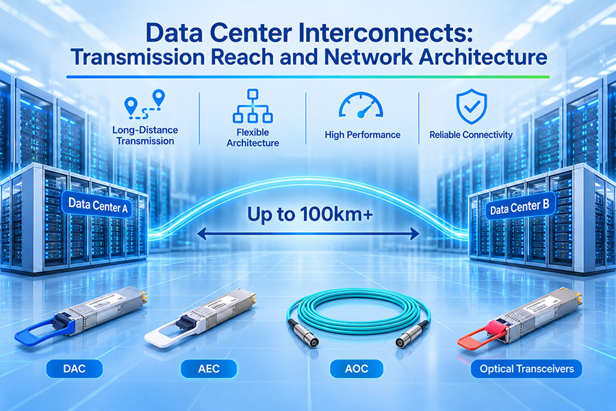
Cloud computing, AI infrastructure, distributed storage, and large-scale enterprise applications increasingly depend on high-capacity connections between geographically separated data centers. These connections must transport large volumes of traffic while maintaining predictable latency, high availability, and efficient use of optical fiber.
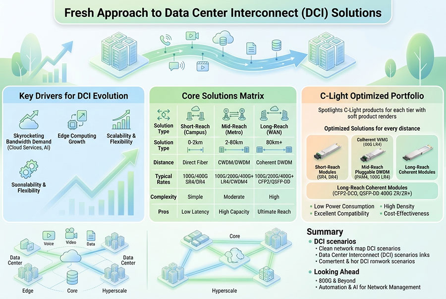
Data Center Interconnect (DCI) provides the optical and network infrastructure required to connect independent data center facilities. Depending on the distance and capacity requirements, a DCI deployment may use direct fiber connections, dedicated optical wavelengths, coherent pluggable transceivers, or a larger DWDM transport system.
As network speeds advance from 100G and 400G to 800G and 1.6T, DCI architecture is becoming increasingly important. Transmission reach, optical power budget, fiber characteristics, amplification, wavelength planning, and equipment compatibility must be considered together rather than treating the optical transceiver as an isolated component.
1. What Is Data Center Interconnect?
Data Center Interconnect refers to the network infrastructure that links two or more data center locations. It enables applications, storage systems, cloud platforms, and computing resources to communicate across separate facilities.
Unlike connections inside a single data center, DCI links often cover longer distances and may pass through metropolitan or regional fiber networks. They therefore require more careful planning of optical reach, latency, redundancy, and transport capacity.
Data Center to Data Center
Connects separate facilities to support workload distribution, application communication, and shared infrastructure.
Primary and Backup Sites
Provides connectivity between production facilities and disaster recovery locations for data replication and business continuity.
Cloud and Colocation Facilities
Connects cloud infrastructure, carrier-neutral facilities, and enterprise networks across different buildings or campuses.
AI and High-Performance Computing
Supports distributed storage, data movement, and communication between computing facilities in large-scale AI infrastructure.
The main objective is to provide sufficient bandwidth and reliable connectivity while controlling latency, optical transmission costs, and operational complexity.
2. DCI Transmission Distance and Application Scenarios
Transmission distance is one of the first factors considered during DCI design. A short campus connection may require only direct optical connectivity, while a metropolitan or regional link may need coherent transmission and optical amplification.
| DCI Scenario | Typical Distance Range | Common Optical Approach | Primary Design Focus |
|---|---|---|---|
| Intra-campus DCI | Under 2 km | Direct fiber, Ethernet optics, or suitable short-reach coherent interfaces | Port density, fiber routing, and latency |
| Short-reach DCI | 2–10 km | Single-mode Ethernet optics or fixed-wavelength coherent solutions | Optical loss and host compatibility |
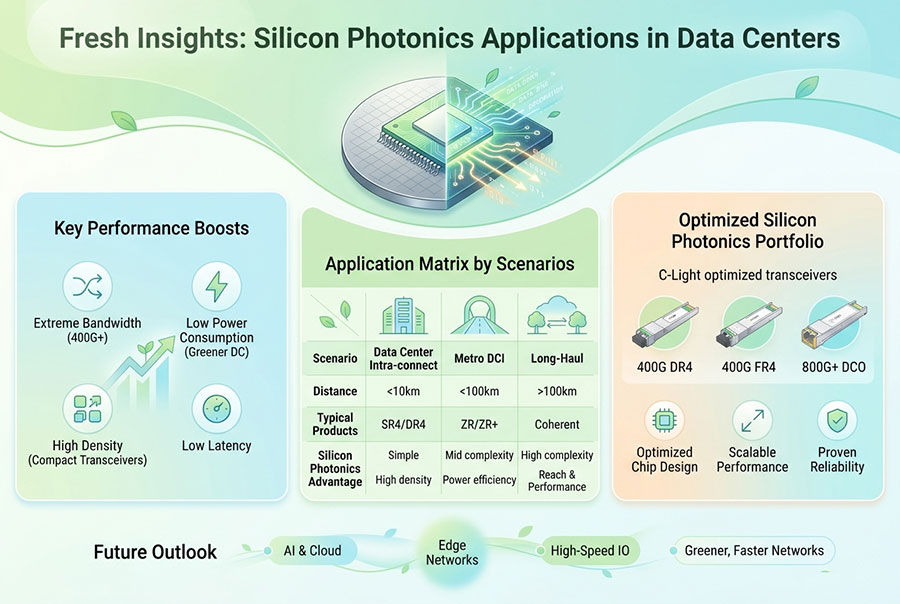
| Metro DCI | 10–80 km | Long-reach optics, coherent pluggables, or DWDM | Fiber quality, dispersion, and optical budget |
| Extended Metro DCI | 80–120 km | Coherent optics with an appropriate amplified or engineered line system | Amplification, OSNR, and link engineering |
| Regional DCI | 120–500 km and beyond | Coherent transport with DWDM, amplification, and potentially ROADM systems | Optical performance, latency, and wavelength management |
These are planning categories, not guaranteed distances for every optical module. A 10 km or 40 km Ethernet transceiver does not automatically support the same reach when connected through additional patch panels, multiplexers, or a different fiber route.
3. Common DCI Network Architectures
DCI can be deployed using different architectures depending on distance, traffic volume, fiber availability, and operational requirements. Three common approaches are direct point-to-point connectivity, DWDM-based transport, and routed optical networking.
Direct Point-to-Point Fiber
A direct point-to-point connection uses dedicated fiber strands between two data center locations. Each endpoint connects to the optical interface at the opposite facility.
This architecture is straightforward and can offer low operational complexity. It is suitable when dedicated fiber is available and the required reach fits the selected optical interface.
DWDM-Based DCI
Dense Wavelength Division Multiplexing allows multiple optical channels to share one fiber pair. Each channel operates at a different wavelength, increasing the capacity of existing fiber infrastructure.
Router / Switch
Router / Switch
DWDM is particularly useful when multiple high-capacity connections must operate over limited fiber resources. Optical amplifiers and wavelength management equipment may be added according to the link design.
Routed Optical Networking
In a routed optical architecture, coherent optical modules can be installed directly into compatible routers or switches. The electrical client traffic is mapped into a coherent optical signal that travels over the line system.
This approach can reduce the number of separate transponder devices and simplify the connection between packet networking and optical transport. However, platform support, coherent mode compatibility, optical power, and line-system requirements must be verified.
4. Optical Transceiver Types for DCI
Different optical transceiver technologies serve different distance and network requirements. The most important distinction is between conventional Ethernet client optics and coherent optical modules designed for transmission over longer fiber routes.
| Optical Type | Typical Application | Transmission Approach | DCI Suitability |
|---|---|---|---|
| SR4 / SR8 | Short-reach data center links | Parallel multimode fiber | Primarily intra-data-center connectivity |
| DR4 / DR8 | Short-reach single-mode links | Parallel single-mode fiber | Suitable for short DCI routes within the supported reach |
| FR4 / 2FR4 | Single-mode Ethernet links | Wavelength multiplexing within the module | Useful for selected campus and short DCI applications |
| LR4 | Longer-reach Ethernet links | Multiple wavelengths over single-mode fiber | Suitable for certain short and medium-distance connections |
| ZR | Coherent DCI | Single-wavelength coherent transmission | Designed for amplified point-to-point DCI applications |
| ZR+ | Extended metro and regional DCI | Coherent transmission with enhanced line-system capabilities | Suitable for longer distances when the selected mode and system support them |
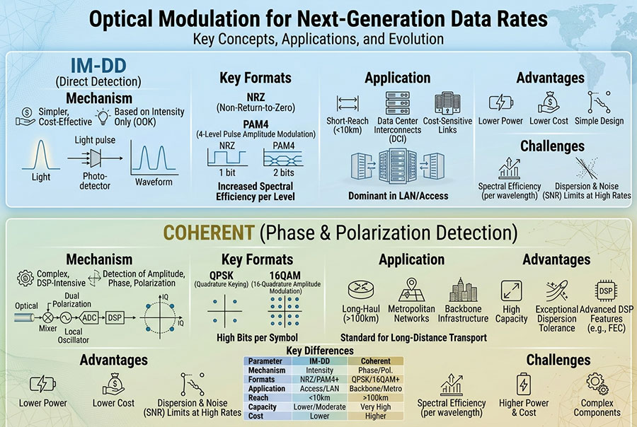
Conventional SR8, DR8, FR4, and LR4 modules should not be confused with coherent ZR or ZR+ optics. Their modulation, optical interfaces, reach characteristics, and line-system requirements are different.
5. 400G DCI: Coherent Transmission and Network Design
400G DCI is an important architecture for connecting high-capacity data centers. The introduction of coherent pluggable modules allows 400GbE client traffic to be transported over a single optical wavelength, reducing dependence on separate large transponder systems in supported deployments.
400ZR is an Optical Internetworking Forum (OIF) coherent interface designed for single-span, amplified DWDM links in the approximate 80–120 km application range. Its specifications define the coherent line interface and interoperability requirements.
For routes that exceed the baseline 400ZR application, 400ZR+ and OpenZR+ implementations can provide additional operating modes and reach flexibility. The achievable distance depends on the selected mode, optical line system, fiber characteristics, and engineering margin.
400ZR
Designed for interoperable 400G coherent transmission over amplified point-to-point DWDM links. It is commonly associated with metro DCI between nearby data center facilities.
400ZR+
Extends coherent pluggable capabilities through additional operating modes and optical performance options for selected metro and regional transport applications.
Typical 400G DCI design considerations include:
Compatibility between the coherent module and the router or switch host.
Supported modulation, FEC, baud rate, and line-side interface.
DWDM channel spacing and wavelength configuration.
Optical launch power and receiver operating range.
Amplifier gain, noise figure, and optical signal-to-noise ratio.
Fiber attenuation, chromatic dispersion, and polarization-related effects.
6. 800G DCI: Increasing Capacity per Wavelength
As AI training, distributed storage, and cloud infrastructure generate more traffic between data center facilities, 800G DCI provides a higher-capacity optical transport option.
800ZR is defined by an OIF Implementation Agreement for 800G coherent line transmission over amplified single-span DWDM links in the 80–120 km application range. It provides a standardized coherent interface for high-capacity DCI applications.
800ZR+ and other extended-reach coherent implementations target longer metro and regional networks. These implementations may support different data rates and reach modes depending on the platform, optical design, and network conditions.
| Technology | Line Capacity | Typical Application | Key Design Consideration |
|---|---|---|---|
| 400ZR | 400G | Single-span amplified DCI | OIF interoperability and optical line budget |
| 400ZR+ | Up to 400G in supported modes | Extended metro and regional DCI | Mode selection and line-system compatibility |
| 800ZR | 800G | Higher-capacity single-span DCI | Coherent performance and amplified DWDM design |
| 800ZR+ | Up to 800G in supported modes | High-capacity metro and regional transport | Reach, modulation, FEC, and optical infrastructure |
The distinction between 800G client optics and 800G coherent optics is important. An 800G SR8 or DR8 module is designed for a specific parallel optical interface and short-reach application. An 800ZR module uses coherent transmission for a different type of optical line connection.
7. The Development of 1.6T Coherent DCI
As network traffic continues to grow, the next generation of DCI technology is moving toward higher capacity per wavelength. A 1.6T coherent line interface can potentially transport twice the capacity of an 800G wavelength, helping increase fiber utilization and reduce the number of individual optical channels required for a given traffic volume.
In September 2026, OIF announced its 1600ZR Implementation Agreement. The specification defines an interoperable 1.6T coherent line interface for single-span, amplified, point-to-point DWDM links up to 120 km.
This development provides a standards-based foundation for future 1.6T coherent DCI implementations. Commercial deployment still depends on module availability, host platform support, optical line-system compatibility, power consumption, and operational qualification.
8. Transmission Reach: What Determines the Actual Distance?
Optical transmission reach is determined by the combined performance of the transceiver and the complete optical path. The nominal distance printed on a module specification is based on defined operating conditions. Real network routes may introduce additional losses and signal impairments.
Fiber Attenuation
Fiber attenuation reduces optical power as the signal travels along the link. The total loss depends on fiber length, wavelength, fiber characteristics, and the number of optical connections.
Connector and Splice Loss
Patch panels, adapters, splices, and intermediate distribution points introduce additional loss. These values must be included in the optical link budget.
Chromatic Dispersion
Chromatic dispersion causes different spectral components of an optical signal to propagate at different speeds. It can affect signal quality over longer transmission distances, especially when the system has limited dispersion tolerance.
Polarization Effects
Polarization mode dispersion and other polarization-related effects can affect high-speed optical signals. Coherent receivers and DSP techniques help compensate for selected impairments, but the overall system still has performance limits.
Optical Signal-to-Noise Ratio
Optical amplifiers increase signal power but also introduce noise. In amplified DWDM systems, OSNR is an important factor in determining whether the receiver can maintain the required signal quality.
| Parameter | Effect on Transmission | Design Consideration |
|---|---|---|
| Fiber attenuation | Reduces received optical power. | Calculate the complete end-to-end loss. |
| Connector loss | Consumes available optical margin. | Include every connection point in the route. |
| Chromatic dispersion | Distorts the received signal. | Check module and system dispersion tolerance. |
| PMD | Can affect signal integrity over long routes. | Consider fiber characteristics and coherent DSP capability. |
| OSNR | Determines the signal quality after optical amplification. | Evaluate amplifier noise and channel loading. |
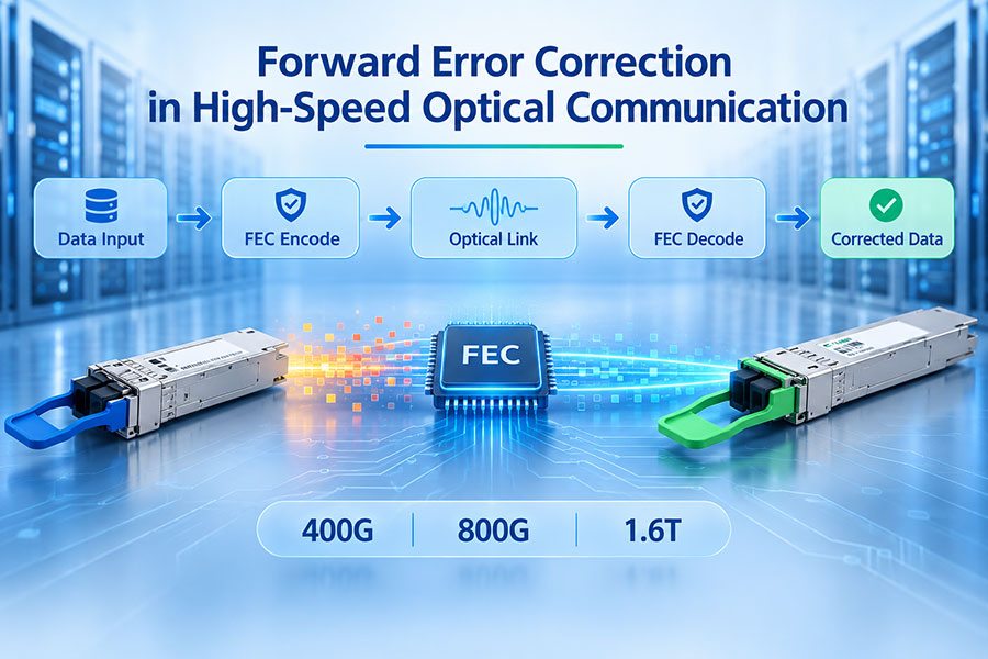
| FEC performance | Provides error correction within the supported operating range. | Check pre-FEC BER, post-FEC performance, and receiver margin. |
9. DWDM, Optical Amplifiers, and Line Systems
DWDM is widely used in DCI networks because it allows multiple high-capacity channels to operate over the same fiber pair. Each channel uses a designated wavelength or frequency slot, and a multiplexer combines the channels onto the transmission fiber.
At the receiving end, a demultiplexer separates the wavelengths and directs each channel to its corresponding optical receiver.
For longer routes, optical amplifiers may be required to compensate for fiber attenuation. Their placement and configuration depend on the span loss, required output power, channel count, and overall line-system design.
Coherent Transceiver
Coherent Transceiver
Remote Receiver
Remote Receiver
Common optical transport components include:
DWDM multiplexers and demultiplexers: Combine and separate optical wavelengths.
EDFA amplifiers: Compensate for optical power loss in supported C-band or other designed optical systems.
ROADM: Allows selected wavelengths to be added, dropped, or routed through an optical network.
Optical Supervisory Channel: Supports monitoring and management functions in compatible line systems.
Optical monitoring equipment: Helps observe channel power, wavelength, and transmission conditions.
The use of an amplifier does not automatically guarantee a longer reach. Amplifier noise, gain flatness, channel loading, receiver sensitivity, and nonlinear effects must also be considered.
10. DCI Network Redundancy and Availability
Data center connectivity often carries critical applications, storage replication, and business services. A single optical route may be insufficient when network availability is a major requirement.
Redundancy can be implemented at the fiber, optical transport, and packet networking layers. The correct design depends on the required availability target, route diversity, recovery time, and cost.
Dual Fiber Routes
Separate physical fiber paths can reduce the risk of a single cable cut disrupting both connections. Route diversity must be verified rather than assumed.
Dual Optical Systems
Independent line systems or optical equipment can provide additional protection against equipment-level failures.
Packet Layer Redundancy
Routing and switching protocols can support traffic recovery when a connection or transport path becomes unavailable.
Monitoring and Fault Management
Optical power, FEC statistics, alarms, and link status help operators detect faults and assess network conditions.
Redundant links should be evaluated for shared-risk link groups. Two fiber pairs that follow the same physical duct may still be affected by the same construction damage or facility incident.
11. DCI Latency and Bandwidth Planning
DCI performance is not determined by bandwidth alone. Latency becomes especially important for distributed databases, storage replication, synchronous services, and applications that communicate frequently between facilities.
Fiber propagation introduces distance-related delay. Equipment processing, optical transport, switching, routing, and network congestion add further latency.
For standard single-mode fiber, a useful planning approximation is about 5 microseconds of one-way propagation delay per kilometer. Actual values depend on the fiber route and physical propagation characteristics.
| Fiber Route Length | Approximate One-Way Propagation Delay | Approximate Round-Trip Propagation Delay |
|---|---|---|
| 10 km | 50 µs | 100 µs |
| 20 km | 100 µs | 200 µs |
| 50 km | 250 µs | 500 µs |
| 80 km | 400 µs | 800 µs |
| 100 km | 500 µs | 1 ms |
These figures represent approximate fiber propagation delay only. They exclude switching, routing, FEC processing, optical equipment, and other network overhead. The actual route length may also be longer than the straight-line distance between two data centers.
Bandwidth planning should consider both the current traffic demand and future growth. A DCI system may need to support storage replication, virtual machine migration, backup traffic, AI dataset movement, and inter-site application communication simultaneously.
12. Selecting the Right DCI Optical Solution
Choosing an optical solution requires matching the transmission technology to the actual network environment. A short campus link and a regional DWDM route have different requirements even if both carry the same Ethernet client rate.
| Selection Factor | Questions to Evaluate |
|---|---|
| Transmission distance | Is the route within a short-reach, metro, or regional application? |
| Data rate | Is the required client capacity 100G, 400G, 800G, or 1.6T? |
| Fiber infrastructure | Is dedicated fiber available, or must multiple wavelengths share existing fiber? |
| Optical architecture | Is direct detection sufficient, or is coherent transmission required? |
| Amplification | Does the route require an EDFA or a complete optical line system? |
| Host compatibility | Does the switch or router support the selected transceiver and coherent mode? |
| Latency | What is the maximum acceptable one-way and round-trip delay? |
| Redundancy | Are physically diverse routes and independent equipment required? |
| Operating cost | What are the power, cooling, fiber, equipment, and maintenance requirements? |
For a short DCI connection, conventional single-mode Ethernet optics may provide a simpler and more economical design. For amplified metro DCI, coherent pluggables can provide high capacity over a single wavelength. Longer regional routes may require enhanced coherent modes and a dedicated optical transport architecture.
13. C-LIGHT Optical Transceiver Solutions for DCI Infrastructure
C-LIGHT provides high-speed optical connectivity products for data center, AI infrastructure, and enterprise networking applications. Different product families support different parts of the optical network, from short-reach data center connections to selected single-mode links and high-bandwidth interconnect platforms.
400G QSFP-DD Optical Transceivers
The 400G QSFP-DD product family supports high-bandwidth optical connectivity for compatible network equipment. Available optical configurations should be selected according to the required reach, fiber type, and interface architecture.
View 400G QSFP-DD Products400G OSFP Optical Transceivers
400G OSFP modules support selected high-speed data center and network interconnect applications. Verify the specific optical interface and host platform before using a product for a DCI route.
View 400G OSFP Products800G OSFP Optical Transceivers
Designed for 800G network platforms and high-density data center connectivity. Different SR8, DR8, and 2FR4 configurations serve different fiber and reach requirements.
View 800G OSFP Products800G QSFP-DD Optical Transceivers
High-bandwidth optical interfaces for compatible 800G network platforms. Product selection should account for the required optical reach, connector type, and system compatibility.
View 800G QSFP-DD ProductsFor coherent DCI applications, customers should specifically confirm whether the required module is a 400ZR, 400ZR+, 800ZR, or another coherent implementation. A conventional 400G or 800G client optical module should not be assumed to support coherent DWDM transmission simply because its data rate matches the DCI capacity.
14. Conclusion
Data Center Interconnect is a key part of modern cloud, AI, and enterprise network infrastructure. Its design requires a balance between transmission reach, bandwidth, latency, optical performance, fiber utilization, and network availability.
Direct fiber connections can provide a straightforward solution for short-distance links, while DWDM and coherent optical technologies support higher-capacity metro and regional connectivity. The development of 400ZR, 800ZR, and 1600ZR continues to expand the role of pluggable coherent optics in data center transport.
Successful DCI deployment depends on matching the optical module to the complete network architecture. Fiber characteristics, optical budget, amplification, host compatibility, redundancy, and operational monitoring must all be considered during planning and qualification.
15. Frequently Asked Questions
DCI connects geographically separated data centers so that applications, storage systems, cloud platforms, and computing resources can exchange traffic over high-capacity network links.
Ordinary data center networking often connects servers, switches, and storage within a facility. DCI focuses on communication between separate data center locations, where longer fiber routes, optical transport, latency, and route redundancy become more important.
400ZR is an OIF coherent interface designed for amplified single-span DCI. 400ZR+ implementations add extended operating modes and performance options for selected metro and regional transport applications.
It may be suitable for short-reach connections within its specified optical reach, but it is not equivalent to an 800ZR coherent module. SR8 uses parallel optical transmission, while 800ZR is designed for coherent single-wavelength transport over amplified DWDM links.
DWDM is useful when multiple high-capacity optical channels need to share limited fiber resources. It can also form part of an amplified optical transport system for longer metro and regional connections.
Amplification can compensate for fiber attenuation, but it also introduces noise and does not remove all transmission impairments. Reach depends on the complete optical link design, including OSNR, dispersion, receiver performance, and FEC.
800ZR defines an 800G coherent line interface for amplified DCI applications. The OIF 1600ZR agreement defines a 1.6T coherent line interface, increasing the capacity per wavelength for supported single-span DWDM links.
Verify data rate, transmission distance, fiber type, wavelength, optical power budget, host compatibility, modulation, FEC, and whether the application requires direct detection or coherent transmission.
Build High-Capacity Optical Connectivity
C-LIGHT provides optical transceiver solutions for modern data center and high-speed networking applications. Contact our team for product selection, optical interface requirements, and network compatibility support.
Contact C-LIGHT >

 >
 >
 >
 >
 >
 >
 >