TEL:+86 132 6656 7067





As data traffic grows across cloud platforms, data centers, telecommunications networks, and enterprise infrastructure, fiber capacity has become a critical network resource. Dense Wavelength Division Multiplexing (DWDM) allows multiple optical channels to share the same fiber, increasing aggregate transmission capacity without requiring a separate fiber pair for every service.
1. How DWDM Technology Increases Fiber Capacity
A conventional optical link typically carries data through one optical wavelength on a fiber. DWDM expands this architecture by assigning multiple optical wavelengths to separate data channels. Each channel carries its own signal, and an optical multiplexer combines them into a composite signal for transmission over the same fiber.
At the receiving end, a demultiplexer separates the composite signal into individual wavelengths. Each wavelength is then delivered to its corresponding optical receiver or transceiver.
For example, a system carrying 40 independent 10G channels can provide an aggregate nominal channel capacity of 400G. Increasing the number of channels or the data rate per wavelength can further raise the total capacity, provided the optical spectrum, transmission equipment, and fiber characteristics support the design.
The main advantage is more efficient use of installed fiber. Network operators can expand transmission capacity while reducing the need for additional physical fiber routes.
2. DWDM Optical Transceiver Architecture
A DWDM transceiver integrates the optical transmitter and receiver functions into a pluggable module. Its transmitter operates at a defined wavelength or tunable frequency, while its receiver detects the incoming optical signal and converts it back into an electrical interface.
Optical Transmitter
Generates a controlled optical carrier and modulates it with the electrical data signal. Wavelength stability is essential for maintaining the assigned DWDM channel.
Optical Receiver
Detects the incoming optical signal and converts it into an electrical signal. Receiver sensitivity and overload limits influence the usable link budget.
Digital Monitoring
Depending on the module, diagnostic functions can report temperature, supply voltage, transmit power, receive power, and other operating parameters.
The transceiver's optical characteristics must match the optical line system. These characteristics include wavelength or frequency, channel spacing, transmit power, receiver sensitivity, spectral properties, and supported modulation format.
3. Fixed-Wavelength and Tunable DWDM Transceivers
DWDM modules are commonly available in fixed-wavelength and tunable configurations. The choice affects channel planning, spare inventory, deployment flexibility, and maintenance.
| Characteristic | Fixed-Wavelength DWDM | Tunable DWDM |
|---|---|---|
| Channel selection | Configured for a specific wavelength or ITU channel | Can be configured across a supported tuning range |
| Deployment | Requires the correct channel-specific module for each link | Allows channel assignment through module configuration |
| Inventory | May require multiple wavelength-specific spare modules | Can reduce the number of spare module variants required |
| Network planning | Channel allocation is determined during equipment selection | Channel allocation can be adjusted within the supported tuning range |
| Typical applications | Access, metro, and fixed-channel optical links | Flexible metro, transport, and coherent DWDM systems |
Fixed-wavelength modules are suitable for networks with stable channel assignments. Tunable modules are useful when operators need greater flexibility for wavelength allocation, network expansion, or equipment replacement.
Tunable capability does not mean that a module can operate on every DWDM grid or optical line system. Its supported frequency range, channel spacing, output power, modulation format, and interoperability requirements must still be checked.
4. DWDM Channel Spacing and the ITU Frequency Grid
DWDM channels are arranged according to an optical frequency grid. ITU-T G.694.1 defines the DWDM frequency grid, including fixed channel spacing and flexible-grid arrangements. The reference frequency is 193.1 THz.
Common fixed-grid spacing values include 100 GHz and 50 GHz. Narrower spacing can accommodate more channels within a given spectral range, but it also places greater demands on transmitter stability, filtering, and system engineering.
| Channel Spacing | General Network Consideration | Design Implication |
|---|---|---|
| 100 GHz | Relatively wider separation between adjacent channels | Common in traditional fixed-grid DWDM deployments |
| 50 GHz | Higher potential channel density | Requires compatible transceivers and optical filters |
| 25 GHz and narrower slots | Used in selected high-density or flexible-grid designs | Requires coordinated spectral planning and compatible equipment |
| Flexible grid | Allows different frequency-slot widths | Supports channel allocation based on signal spectral requirements |
A channel's frequency and wavelength are related, but optical network planning is generally based on frequency. The approximate wavelength can be calculated using the speed of light divided by the optical frequency. Because the relationship is inverse, higher optical frequencies correspond to shorter wavelengths.
5. Common DWDM Transceiver Types and Data Rates
DWDM technology covers several generations of optical modules. The appropriate form factor and data rate depend on the network architecture, transmission distance, host equipment, and whether the application uses direct-detect or coherent optics.
| Module Category | Typical Network Role | Key Selection Factors |
|---|---|---|
| 10G DWDM SFP+ | Metro Ethernet, enterprise aggregation, and transport links | Wavelength, channel spacing, reach, and optical budget |
| 25G DWDM SFP28 | Higher-speed access and aggregation networks | Host compatibility, channel plan, and link budget |
| 100G DWDM QSFP28 | High-capacity aggregation and selected transport applications | Optical interface type, wavelength, and transmission design |
| 400G Coherent QSFP-DD | High-capacity data center interconnect and metro DWDM | Coherent standard, modulation, line-system compatibility, and power |
The categories above represent different implementation approaches rather than interchangeable modules. A 10G fixed-wavelength DWDM SFP+ and a 400G coherent QSFP-DD have different optical architectures, host interfaces, power requirements, and line-system requirements.
For higher-capacity links, coherent pluggables such as 400ZR and 400ZR+ can integrate digital coherent optics into router or switch platforms. Their supported reach depends on the specific implementation and optical line system rather than the data rate alone.
6. Direct-Detect DWDM and Coherent DWDM
Direct-detect and coherent technologies are both used in wavelength-division multiplexing networks, but they address different transmission requirements.
| Parameter | Direct-Detect DWDM | Coherent DWDM |
|---|---|---|
| Detection method | Typically uses direct optical detection | Uses coherent detection with a local optical reference |
| Signal processing | Depends on the module's direct-detect architecture | Uses coherent DSP for signal recovery and compensation |
| Common applications | Fixed-channel access and metro links | High-capacity DCI, metro, and long-haul transport |
| Design priorities | Wavelength accuracy, optical power, and receiver sensitivity | OSNR, modulation, FEC, dispersion, and line-system performance |
| System complexity | Generally simpler for suitable short and metro applications | More advanced optical and digital signal processing |
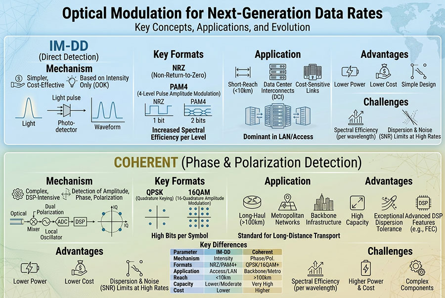
Coherent transmission can encode more information into an optical carrier through advanced modulation and polarization-based signal processing. This makes it suitable for high-capacity transmission where spectral efficiency and optical reach are important.
However, coherent modules require careful attention to host compatibility, software support, power consumption, thermal limits, FEC implementation, and optical line-system parameters. A coherent transceiver should not be selected solely because its nominal data rate is higher.
7. Optical Mux, Demux, Amplifiers, and Line Systems
A DWDM transceiver is only one part of a complete wavelength-division multiplexing system. The optical line infrastructure determines how multiple channels are combined, transmitted, amplified, and separated.
DWDM Mux and Demux
The multiplexer combines individual wavelengths onto a common fiber. The demultiplexer separates them at the receiving location.
EDFA Amplifier
Erbium-Doped Fiber Amplifiers compensate for optical signal attenuation in suitable C-band transmission systems. Amplifier gain and noise must be engineered.
OADM and ROADM
Optical add/drop equipment allows selected wavelengths to enter or leave a network node. ROADMs provide remotely configurable wavelength routing.
In a basic point-to-point arrangement, a pair of mux/demux devices can combine and separate multiple wavelengths over a fiber route. Longer or more demanding links may require optical amplification, dispersion management where applicable, and additional line-system components.
An optical line system can also include monitoring points, gain equalization, optical channel supervision, and protection mechanisms. These functions help maintain consistent channel performance as network capacity increases.
8. Transmission Distance and Optical Power Budget
DWDM transmission distance is determined by the complete optical path rather than the transceiver label alone. Fiber attenuation, connector loss, splice loss, mux/demux insertion loss, amplifier performance, and receiver characteristics all contribute to the link design.
For a basic power-budget calculation:
The calculated budget must cover the total path loss and any required engineering margin. For amplified DWDM systems, the design must also account for amplifier gain, noise figure, optical signal-to-noise ratio (OSNR), and other line-system constraints.
| Design Parameter | What It Affects |
|---|---|
| Transmit optical power | Available signal level entering the optical path |
| Receiver sensitivity | Minimum received signal level for the specified performance |
| Mux/demux insertion loss | Signal attenuation introduced by wavelength filtering components |
| Fiber attenuation | Signal loss accumulated along the fiber route |
| Connector and splice loss | Additional attenuation at physical connection points |
| OSNR | Signal quality relative to optical noise, particularly important for coherent systems |
| Engineering margin | Allowance for aging, repairs, environmental changes, and measurement variation |
For unamplified links, the receiver power budget is a major consideration. For amplified coherent links, a sufficient power level alone does not guarantee successful transmission. OSNR, nonlinear effects, filter characteristics, and the transceiver's supported optical performance must also be evaluated.
9. DWDM Applications in Modern Fiber Networks
DWDM is used wherever multiple high-capacity services need to share limited fiber resources. Its deployment can support both service-provider infrastructure and private optical networks.
Data Center Interconnect
Connects geographically separated data centers with high-capacity optical links for storage replication, cloud infrastructure, and distributed computing.
Telecommunications
Aggregates traffic from access and metro networks into high-capacity transport infrastructure.
Enterprise Networks
Allows organizations with multiple campuses or facilities to expand optical capacity over existing fiber routes.
Cloud Infrastructure
Supports high-bandwidth connections between cloud regions, data centers, and network aggregation locations.
Research and Education
Provides dedicated optical transport capacity for distributed computing, research data exchange, and high-performance network services.
Carrier Backbone
Combines many optical channels to support large volumes of traffic across regional and long-distance fiber infrastructure.
10. DWDM vs. CWDM: Choosing the Right Wavelength Technology
Coarse Wavelength Division Multiplexing (CWDM) and DWDM both transmit multiple optical channels over a shared fiber. Their main differences relate to channel spacing, wavelength planning, optical component requirements, and deployment scale.
| Feature | CWDM | DWDM |
|---|---|---|
| Channel spacing | Typically 20 nm | Much narrower frequency-based spacing, commonly 100 GHz or 50 GHz |
| Channel density | Lower | Higher |
| Wavelength planning | Relatively straightforward | Requires more precise channel and frequency allocation |
| Optical filtering | Generally wider passbands | More selective filtering is required |
| Typical use | Enterprise, access, and moderate-capacity metro links | High-capacity metro, carrier, and backbone networks |
CWDM can be an effective choice when the required channel count is moderate and the network prioritizes straightforward deployment. DWDM is more suitable when operators need to maximize the number of channels and aggregate capacity available on existing fiber.
The decision should be based on required capacity, available fiber, transmission distance, upgrade plans, and total system cost rather than channel density alone.
11. Key Factors When Selecting DWDM Optical Transceivers
A suitable DWDM module must match the electrical host interface and the optical transmission system. The following factors should be checked before deployment.
Data rate and form factor: Confirm whether the equipment requires SFP+, SFP28, QSFP28, QSFP-DD, or another supported module type.
Wavelength or frequency: Match the module to the assigned ITU channel and the corresponding mux/demux port.
Channel spacing: Verify compatibility with the fixed or flexible DWDM grid used by the optical line system.
Transmission distance: Evaluate fiber loss, component insertion loss, receiver sensitivity, and system margin.
Optical interface: Confirm connector type, fiber type, transmit power, and receive specifications.
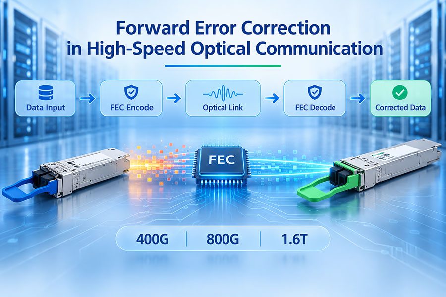
Modulation and FEC: For high-speed coherent modules, verify the supported modulation modes and forward error correction requirements.
Host compatibility: Check port support, firmware, module coding, electrical interface, and power limits.
Thermal requirements: Confirm that the switch or router can provide sufficient cooling for the selected module.
Monitoring: Check available digital diagnostics and alarm functions for operational maintenance.
Compatibility should be verified at both ends of the link. Two modules with the same nominal data rate may still use different wavelengths, optical interfaces, modulation formats, or transmission specifications.
12. C-LIGHT Optical Connectivity for High-Capacity Networks
High-capacity optical networks often combine wavelength transport with high-speed client-side connectivity. The optical transport layer carries multiple channels across the fiber infrastructure, while switches, routers, and data center equipment connect services through high-speed Ethernet interfaces.
For high-speed client-side connectivity and aggregation, the 400G QSFP-DD optical transceiver family provides a range of 400G interface options. The exact optical variant should be selected according to the required reach, fiber type, connector, and host platform.
The 400G OSFP optical transceiver family supports high-bandwidth connectivity in compatible network equipment. It can be considered when designing high-capacity switching and data center interfaces alongside the DWDM transport layer.
For next-generation high-density network interfaces, the 800G QSFP-DD optical transceiver family supports higher client-side bandwidth requirements in compatible platforms. Its role in a DWDM-based architecture depends on the selected optical interface and the design of the transport system.
The 800G OSFP optical transceiver family provides high-speed connectivity options for compatible data center and network platforms. Module selection should account for transmission distance, fiber infrastructure, power consumption, and system compatibility.
These product families address high-speed optical connectivity at the equipment interface. They should not automatically be treated as DWDM line-side modules: the specific product variant must explicitly support the intended wavelength plan and optical transport architecture.
13. Deployment Challenges and Network Optimization
As the number of DWDM channels increases, network planning becomes more demanding. Small differences in optical performance can affect adjacent channels, particularly in systems using narrow channel spacing or advanced modulation.
Common engineering challenges include:
Wavelength mismatch: An incorrect channel assignment can prevent the signal from passing through the intended mux/demux path.
Insufficient optical margin: Excessive path loss can reduce received power below the receiver's operating requirements.
OSNR degradation: Amplifier noise and accumulated optical noise can limit coherent transmission performance.
Filter incompatibility: The mux/demux passband may not match the transceiver's spectral characteristics.
Thermal constraints: High-density modules can increase equipment power and cooling requirements.
Interoperability issues: Different vendors' modules and line systems may require specific optical interface and management compatibility.
A practical optimization process includes channel inventory management, optical power measurements, end-to-end loss verification, OSNR evaluation where applicable, and monitoring of module diagnostics. These activities help identify problems before additional wavelengths are introduced.
14. The Role of DWDM in Future Fiber Capacity Expansion
The growth of AI computing, cloud services, distributed data centers, and high-speed enterprise networks is increasing demand for optical transport capacity. DWDM provides a scalable approach by allowing more data channels to share existing fiber infrastructure.
Future network designs will continue to combine higher-rate optical interfaces, coherent pluggable modules, flexible-grid line systems, and more advanced optical monitoring. As transmission rates increase, the relationship between channel bandwidth, modulation, optical spectrum, and signal quality becomes increasingly important.
For network operators, the most effective upgrade strategy is not simply to maximize the number of wavelengths. It is to balance aggregate capacity, transmission reach, optical performance, equipment compatibility, energy consumption, and future expansion requirements.
15. Conclusion
DWDM optical transceivers make it possible to transmit multiple independent optical channels over a shared fiber infrastructure, providing a practical way to expand network capacity without continuously adding new fiber routes. Fixed-wavelength and tunable modules serve different deployment needs, while direct-detect and coherent technologies address different data-rate and transmission requirements.
Successful DWDM deployment depends on coordinated wavelength planning, compatible mux/demux equipment, accurate optical power budgeting, and suitable line-system engineering. With the right combination of optical transceivers and transport components, DWDM can support scalable metro, data center, carrier, and backbone networks.
Frequently Asked Questions
DWDM stands for Dense Wavelength Division Multiplexing. It is a technology that combines multiple optical wavelengths onto one fiber to increase aggregate transmission capacity.
A fixed-wavelength module operates on a specified channel, while a tunable module can be configured to operate on different supported channels within its tuning range.
Yes. A DWDM system can carry different data rates on separate wavelengths when the transceivers, channel plan, optical filters, and line system support the required signal characteristics.
No. Some short or low-loss DWDM links can operate without optical amplification. Longer links or systems with higher insertion loss may require amplifiers, depending on the optical budget and system design.
Not automatically. DWDM and CWDM use different wavelength plans and channel spacing. The transceiver wavelength and optical filtering components must be designed for the same system.
Verify the host platform, data rate, wavelength or frequency, channel spacing, connector, fiber type, optical power budget, and compatibility with the mux/demux and line system.
Build Reliable High-Capacity Optical Networks
Looking for optical transceivers and high-speed connectivity solutions for your network deployment? Contact our team to discuss product specifications and compatibility requirements.
Contact C-LIGHT >

 >
 >
 >
 >
 >
 >
 >