TEL:+86 132 6656 7067





As data center networks move from 400G to 800G Ethernet, switch designers are under pressure to increase aggregate bandwidth without proportionally increasing rack space, power consumption, and cabling complexity. Doubling the bandwidth of an individual port provides a way to increase network capacity while making more efficient use of front-panel space.
However, 400G vs 800G port density involves more than the bandwidth printed on a transceiver. Physical port count, aggregate switching capacity, module form factor, electrical lane architecture, breakout capability, and thermal design all influence the final result. An 800G switch can provide twice the bandwidth of a 400G switch with the same number of ports, or deliver equivalent aggregate bandwidth using fewer physical ports.
1. What Is Port Density in 400G and 800G Switches?
Port density refers to the number of physical network interfaces available within a specific switch chassis or rack space. In high-speed Ethernet environments, bandwidth density is equally important because it measures how much aggregate network capacity can be delivered within the same physical space.
These two measurements should be evaluated separately:
Physical port density: The number of individual Ethernet ports installed on the switch front panel.
Bandwidth density: The total bandwidth available from those ports, often expressed in Tbps per switch or per rack unit.
For example, a switch with 64 × 400G ports provides 25.6 Tbps of nominal aggregate port bandwidth. A switch with 64 × 800G ports provides 51.2 Tbps. Both have 64 physical ports, but the 800G configuration delivers twice the bandwidth.
| Measurement | 400G Port | 800G Port |
|---|---|---|
| Bandwidth per port | 400 Gbps | 800 Gbps |
| Relative bandwidth | 1× | 2× |
| Ports required for 25.6T | 64 | 32 |
| Ports required for 51.2T | 128 | 64 |
| Bandwidth with 64 physical ports | 25.6 Tbps | 51.2 Tbps |
These calculations represent nominal aggregate port bandwidth. They do not guarantee that a particular switch chassis supports the stated port count or switching capacity. Actual configurations depend on the ASIC, system architecture, front-panel layout, and supported port modes.
2. 400G vs 800G: Port Density and Aggregate Bandwidth
The relationship between port speed and switching capacity becomes clearer when comparing systems with equivalent aggregate bandwidth.
A 25.6T switch architecture can be configured with 64 × 400G ports or 32 × 800G ports. Both configurations provide 25.6 Tbps of nominal port bandwidth. Similarly, a 51.2T system can use 128 × 400G ports or 64 × 800G ports.
| Aggregate Bandwidth | 400G Configuration | 800G Configuration | Port Reduction |
|---|---|---|---|
| 12.8T | 32 × 400G | 16 × 800G | 50% |
| 25.6T | 64 × 400G | 32 × 800G | 50% |
| 51.2T | 128 × 400G | 64 × 800G | 50% |
| 102.4T | 256 × 400G | 128 × 800G | 50% |
These examples show why 800G is attractive for high-capacity data center networks. It can reduce the number of physical connections required for a given aggregate bandwidth, potentially simplifying front-panel layouts and cable management.
However, fewer ports do not automatically mean a smaller switch. The 800G system still requires suitable cages, higher-speed electrical interfaces, optical modules, cooling capacity, and a switching ASIC capable of supporting the intended bandwidth.
3. Electrical Lane Architecture: 400G vs 800G
The transition from 400G to 800G involves higher electrical signaling rates and changes to the host-to-module interface. Both generations commonly use PAM4 signaling, but their lane configurations and signaling speeds depend on the specific module and host architecture.
400G electrical architecture
Many 400G QSFP-DD implementations use eight electrical lanes operating at approximately 50 Gbps per lane using PAM4 signaling. This is commonly associated with a 400GAUI-8 host interface.
Some newer 400G implementations use four electrical lanes operating at approximately 100 Gbps per lane. This is associated with 400GAUI-4 and is used in platforms designed around 100G-class SerDes.
800G electrical architecture
Common 800G implementations use eight electrical lanes operating at approximately 100 Gbps per lane using PAM4 signaling. This is associated with 800GAUI-8 and is widely used in OSFP and QSFP-DD800 optical modules.
Other 800G architectures can use four electrical lanes operating at approximately 200 Gbps per lane, depending on the host and module implementation.
| Technical Parameter | 400G | 800G |
|---|---|---|
| Aggregate bandwidth | 400 Gbps | 800 Gbps |
| Common electrical lane count | 8 lanes | 8 lanes |
| Common lane rate | 50 Gbps | 100 Gbps |
| Common host interface | 400GAUI-8 | 800GAUI-8 |
| Alternative lane architecture | 4 × 100G | 4 × 200G on supported platforms |
| Modulation | PAM4 | PAM4 |
| Signal integrity requirements | 50G or 100G-class electrical channels | 100G or 200G-class electrical channels |
The exact electrical interface must be checked against the host ASIC and transceiver specification. A 400G QSFP-DD module using eight 50G electrical lanes is not electrically identical to a 400G QSFP112 module using four 100G electrical lanes, even though both provide the same aggregate data rate.
Higher-speed SerDes also increases the importance of PCB channel quality, connector performance, equalization, clock recovery, and forward error correction. These factors influence the design of 800G switches and their optical interfaces.
4. Form Factor and Front-Panel Design
Physical module dimensions are a major factor in switch port density. The number of optical cages that fit on a front panel depends on the form factor, cage spacing, heat sink design, connector accessibility, and cooling requirements.
400G optical transceivers are commonly available in QSFP-DD and OSFP form factors. QSFP112 is another option for selected 400G implementations using a four-lane 100G electrical interface.
800G transceivers are commonly available in OSFP and QSFP-DD800 form factors. These modules are designed for higher electrical signaling rates and the corresponding mechanical and thermal requirements.
| Form Factor | Typical Data Rate | Electrical Architecture | Typical Application |
|---|---|---|---|
| QSFP-DD | 400G | Commonly 8 × 50G or supported 4 × 100G implementations | 400G Ethernet switching and data center connectivity |
| QSFP112 | 400G | 4 × 100G-class electrical lanes | Selected 400G high-speed switching platforms |
| OSFP | 400G / 800G | Depends on module and host generation | High-density data center and AI networking |
| QSFP-DD800 | 800G | 8 × 100G-class electrical lanes | 800G Ethernet switching |
Although QSFP-DD and QSFP112 share a similar general form-factor family, their electrical interfaces and host requirements differ. Likewise, an 800G module should not be assumed to fit or operate in every OSFP or QSFP-DD cage.
Front-panel density also depends on the cooling arrangement. OSFP modules generally have a larger thermal design envelope than QSFP-DD modules, while specific switch platforms may use different heat sink arrangements. The module must match the cage, airflow, and mechanical requirements defined by the equipment manufacturer.
5. Breakout Connectivity and Port Utilization
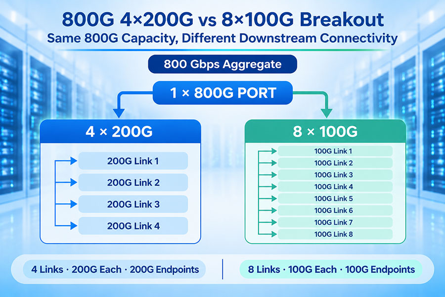
Breakout connectivity allows a high-speed physical switch port to be divided into multiple lower-speed logical links. It provides flexibility when connecting switches to servers, storage systems, and network devices operating at different speeds.
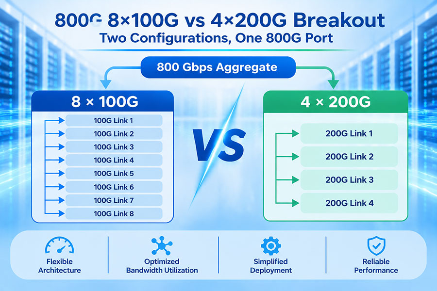
A 400G port can support configurations such as 1 × 400G, 2 × 200G, or 4 × 100G on suitable platforms. An 800G port can support 1 × 800G, 2 × 400G, or 8 × 100G where the host and optical architecture support those modes.
| Physical Port | Possible Breakout Configuration | Application |
|---|---|---|
| 400G | 1 × 400G | Direct 400G switch or server connection |
| 400G | 2 × 200G | Two 200G connections |
| 400G | 4 × 100G | Four 100G server or switch connections |
| 800G | 1 × 800G | Direct 800G connection |
| 800G | 2 × 400G | Two 400G connections |
| 800G | 4 × 200G | Four 200G connections |
| 800G | 8 × 100G | Eight 100G connections where supported |
These are representative breakout configurations rather than universal capabilities. Actual support depends on the switch ASIC, port mode, electrical lane mapping, transceiver design, fiber assembly, and operating system.
Breakout can be especially useful during the transition from 400G to 800G. An 800G-capable switch can potentially connect to existing 400G equipment through supported 2 × 400G configurations, helping operators upgrade network capacity without replacing every endpoint simultaneously.
However, breakout requires compatible optical or electrical hardware at both ends. The physical module and cable assembly must support the intended lane distribution; changing a software setting alone cannot create unsupported optical channels.
6. Power Consumption and Thermal Management
Higher data rates increase the demands placed on optical signal processing and electrical interfaces. Although 800G provides twice the bandwidth of 400G, its power consumption does not necessarily double. Actual module power depends on the optical application, reach, DSP architecture, laser technology, and thermal design.
In a high-density switch, the combined power consumption of all installed modules can become a significant part of the system's thermal load. A switch with 64 × 800G ports may have a substantially different cooling requirement from a system with 64 × 400G ports, even when both use the same chassis size.
| Parameter | 400G Deployment | 800G Deployment |
|---|---|---|
| Module power | Depends on optical application and design | Can be higher due to faster signaling and processing |
| Thermal load | Depends on module count and power class | Requires careful evaluation at high port density |
| Cooling design | Airflow and heat sink requirements vary by platform | Higher-speed modules may require more demanding cooling |
| Port power budget | Must remain within host specifications | Must support the selected 800G module power class |
| System-level efficiency | Depends on total switch and link power | Can improve bandwidth per port, but requires power evaluation |
For a meaningful efficiency assessment, network operators should compare power consumption per Tbps rather than looking only at the power rating of an individual transceiver. Switch ASIC power, cooling overhead, optical module power, and the number of required links all contribute to total system energy consumption.
7. 400G vs 800G in AI Data Center Networks
AI training and inference clusters require high-bandwidth connections between GPU servers, leaf switches, spine switches, and other network infrastructure. As the number of accelerators increases, the network must support greater east-west traffic while maintaining predictable latency and sufficient aggregate capacity.
400G has become an important building block for AI and cloud data center networks. It supports high-speed server connections and switch uplinks, and can be deployed using QSFP-DD, QSFP112, and OSFP optical interfaces depending on the platform.
800G increases the bandwidth available through each physical port. This makes it useful for high-capacity switch-to-switch links, AI cluster fabrics, and next-generation server connectivity.
The choice between the two depends on the network architecture:
400G networks: Suitable for established data center infrastructures, 400G server interfaces, and switching platforms designed around 400G port configurations.
800G networks: Suitable for higher-capacity switching systems, large AI clusters, and network designs requiring more bandwidth per physical connection.
Mixed 400G and 800G networks: Useful for phased upgrades where the switch supports the necessary breakout modes and optical interoperability.
For AI networks, upgrading from 400G to 800G at the switch level does not automatically double end-to-end application throughput. Server NICs, GPU connectivity, intermediate switches, network topology, and oversubscription ratios all influence actual performance.
Network planners should therefore evaluate the complete fabric rather than focusing only on the maximum speed of individual switch ports.
8. Real-World Switch Capacity and Port Configuration
Switch ASIC capacity provides a useful reference for understanding the relationship between 400G and 800G port density. For example, a 25.6T switching system can theoretically support 64 × 400G ports or 32 × 800G ports. A 51.2T system can support 128 × 400G ports or 64 × 800G ports in equivalent aggregate bandwidth configurations.
Commercial switch architectures demonstrate these design options. For example, Marvell's Teralynx 10 product brief lists a 51.2T system example with 64 × 800G ports and a 25.6T example with 64 × 400G ports. These configurations show how different port speeds can be implemented within distinct switching-capacity and chassis designs.
| Switch Capacity | 400G Configuration | 800G Configuration | Design Focus |
|---|---|---|---|
| 12.8T | 32 × 400G | 16 × 800G | Compact high-speed switching |
| 25.6T | 64 × 400G | 32 × 800G | Equivalent aggregate bandwidth |
| 51.2T | 128 × 400G | 64 × 800G | Higher-capacity data center switching |
| 102.4T | 256 × 400G | 128 × 800G | Large-scale high-bandwidth architecture |
These figures are theoretical port-count relationships based on aggregate bandwidth. Actual switch products may use different chassis sizes, port layouts, ASIC configurations, and cooling systems. A 51.2T switch with 64 × 800G ports is not necessarily physically equivalent to a 25.6T switch with 64 × 400G ports.
9. C-LIGHT 400G and 800G Optical Transceiver Solutions
Moving from 400G to 800G requires optical transceivers that match the host electrical interface, optical transmission standard, module form factor, and system thermal requirements. The selection process should consider both the switch port and the remote-end device.
C-LIGHT provides high-speed optical connectivity products for data center and AI networking applications, including:
400G QSFP-DD Optical Transceivers for supported 400G Ethernet and data center interfaces.
400G OSFP Optical Transceivers for compatible high-density networking platforms.
800G QSFP-DD Optical Transceivers for supported 800G switch interfaces.
800G OSFP Optical Transceivers for high-capacity AI and data center connectivity.
800G Active Optical Cables for supported short-reach optical interconnect applications.
800G Active Electrical Cables for compatible short-reach electrical connections.
Before deployment, customers should confirm the switch model, port speed, electrical lane configuration, optical reach, fiber type, connector, power limit, and cooling arrangement. A 400G module cannot be assumed to operate at 800G simply because the physical form factor is similar.
For projects involving mixed 400G and 800G environments, platform-specific compatibility and breakout requirements should be verified before procurement. For product specifications and technical support, Contact C-LIGHT.
10. Conclusion
The transition from 400G to 800G doubles the bandwidth available through an individual physical network port. This enables data center operators to increase aggregate switching capacity without necessarily increasing the number of front-panel ports or physical connections.
At the same aggregate bandwidth, an 800G architecture can theoretically use half the number of physical ports required by a 400G architecture. However, actual port density depends on the switching ASIC, chassis layout, form factor, electrical lane architecture, cooling system, and supported breakout configurations.
400G remains an important option for established data center networks and existing server interfaces, while 800G provides a higher-bandwidth path for large AI clusters and next-generation switching systems. The right choice depends on endpoint speeds, network topology, switching capacity, optical compatibility, and the ability of the infrastructure to support higher-speed electrical and thermal requirements.
 >

 >
 >
 >
 >
 >
 >
 >