TEL:+86 132 6656 7067





As cloud platforms, AI infrastructure and distributed computing environments expand, data centers increasingly need high-capacity connections across metropolitan and regional locations. These links must carry large volumes of Ethernet traffic while controlling equipment cost, rack space, power consumption and operational complexity.
400ZR addresses this requirement through a standardized 400G coherent optical interface designed for data center interconnect applications. By integrating coherent transmission technology into compact pluggable modules, it allows compatible routers and switches to connect directly to DWDM optical line systems without requiring a separate transponder at every endpoint.
1. What Is 400ZR?
400ZR is a 400Gbps coherent optical interface defined by the Optical Internetworking Forum (OIF). It was developed primarily for high-capacity, point-to-point data center interconnect links, particularly in metropolitan environments.
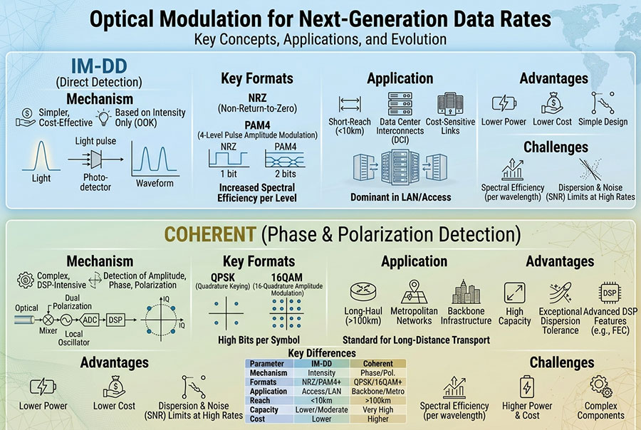
Unlike conventional short-reach 400G optical modules that use parallel or multiple-lane PAM4 transmission, 400ZR uses coherent optical technology to transport a 400GbE signal over a single DWDM wavelength. The coherent receiver processes both the amplitude and phase information of the optical signal, enabling more advanced detection and compensation of transmission impairments.
The OIF 400ZR Implementation Agreement establishes common requirements for important parameters such as modulation, signaling, framing, forward error correction and optical performance. This standardization helps different vendors develop interoperable 400ZR equipment.
2. How 400ZR Works in a DCI Network
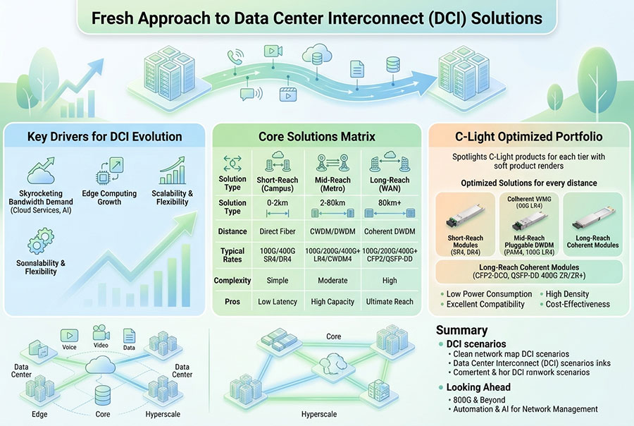
A conventional optical transport architecture may use a client transceiver, an external transponder and a DWDM line system. With a compatible 400ZR implementation, the coherent optical function can be integrated directly into the router or switch interface.
At the transmitting site, the router or switch provides a 400GbE electrical interface to the coherent module. The module's DSP and optical components generate a coherent wavelength suitable for the DWDM line system.
At the receiving site, the remote 400ZR module detects the incoming optical signal, performs coherent signal processing and delivers the recovered Ethernet traffic to the destination device.
This architecture can reduce the need for separate transponder equipment in suitable deployments. However, the DWDM optical line system, channel planning, amplification where required, and network management remain important parts of the overall solution.
3. Key Technical Characteristics of 400ZR
400ZR is designed around a specific balance of transmission capacity, optical performance, interoperability and pluggable-module constraints.
| Parameter | 400ZR Characteristics | Network Relevance |
|---|---|---|
| Client data rate | 400GbE | Connects high-capacity Ethernet router and switch ports. |
| Optical technology | Coherent transmission | Supports high-capacity single-wavelength transport. |
| Modulation | DP-16QAM | Provides high spectral efficiency for the specified application. |
| Line transmission | Single DWDM wavelength | Allows multiple independent channels to share fiber infrastructure. |
| Common form factors | QSFP-DD and OSFP implementations | Enables integration into supported high-density platforms. |
| Optical connector | Typically duplex LC | Connects the module to the optical line system. |
| Standardization | OIF 400ZR Implementation Agreement | Defines a common technical baseline for interoperability. |
Actual module specifications, including power consumption, tuning range, supported wavelength grid and optical performance, vary by implementation. Platform compatibility must also be confirmed independently of the module's form factor.
4. Transmission Distance and Optical Reach
Transmission distance is one of the most important considerations when selecting 400ZR for DCI. The OIF application is associated with amplified point-to-point DWDM links, commonly designed around an 80 km minimum-reach target, with supported implementations and suitable line conditions extending toward 120 km.
Unamplified operation is also possible in suitable configurations, but its practical reach is limited by the module's optical loss budget, fiber attenuation, connector losses and transmission impairments.
| Link Configuration | Typical Design Consideration | Important Factors |
|---|---|---|
| Short unamplified link | Potentially suitable for shorter metropolitan connections | Insertion loss, optical power budget and dispersion. |
| 80 km amplified DWDM | Core 400ZR DCI application range | OSNR, amplifier performance and channel configuration. |
| 80–120 km amplified link | Possible with suitable modules and engineered line conditions | OSNR margin, fiber characteristics and system compatibility. |
| Longer metro or regional links | May require an extended coherent solution | 400ZR+ or other transport technologies may be more appropriate. |
These ranges are design references rather than guaranteed distances for every installation. A link that works over a particular distance in one network may not achieve the same performance in another network with different fiber quality, amplifier placement or channel loading.
5. 400ZR and DWDM Architecture
DWDM allows multiple optical wavelengths to travel through the same fiber, increasing the capacity of existing fiber infrastructure. In a 400ZR DCI system, each coherent module generates a wavelength that occupies a planned channel in the DWDM spectrum.
A typical system may include:
400ZR coherent modules: Generate and receive the 400G optical channels.
DWDM MUX/DEMUX: Combine multiple wavelengths onto a shared fiber and separate them at the receiving site.
Optical amplifiers: Compensate for transmission loss when the link design requires amplification.
Optical line system: Provides the fiber path, channel management and supporting optical functions.
Network management: Monitors optical performance, alarms and operational status.
Because 400ZR is designed for coherent DWDM transmission, channel spacing and optical power planning must be considered together. The selected module must operate within the supported grid and optical conditions of the line system.
6. 400ZR vs. 400ZR+
400ZR and 400ZR+ are related coherent optical technologies, but they address different transmission requirements. 400ZR follows the OIF implementation agreement, while 400ZR+ generally refers to extended-performance solutions based on OpenZR+ MSA specifications and related implementations.
| Feature | 400ZR | 400ZR+ |
|---|---|---|
| Technical basis | OIF 400ZR IA | OpenZR+ MSA and related implementations |
| Primary application | Short-reach DCI | Metro, regional and extended-reach transport |
| Transmission capacity | 400GbE application | Supports additional operating modes depending on implementation |
| Optical performance | Optimized for defined DCI conditions | Additional performance options for more demanding links |
| Network environment | Typically single-span point-to-point DWDM | May support more complex optical transport architectures |
| Selection priority | Standardized 400G DCI connectivity | Extended reach and additional network flexibility |
400ZR+ should not be treated as a single universal specification with identical capabilities across all vendors. Supported line rates, modulation formats, FEC modes, optical reach and interoperability depend on the specific implementation.
7. 400ZR vs. Conventional 400G PAM4 Modules
Both 400ZR coherent modules and conventional 400G PAM4 optical transceivers can carry 400G Ethernet traffic, but their optical interfaces are designed for different network environments.
| Comparison | 400ZR Coherent | Conventional 400G PAM4 |
|---|---|---|
| Transmission method | Coherent optical transmission | Direct-detection PAM4 |
| Optical channel | Single coherent DWDM wavelength | Multiple optical lanes or wavelengths, depending on type |
| Typical applications | Metro DCI and DWDM transport | Data center interconnects and campus links |
| Optical infrastructure | Designed for coherent line systems | Depends on SR, DR, FR, LR or other interface type |
| System considerations | OSNR, wavelength grid, coherent DSP and line-system compatibility | Fiber type, lane mapping, connector and link budget |
For example, a 400G QSFP-DD DR4 module is designed for a short-reach parallel-fiber application. A 400ZR module is designed to generate a coherent wavelength for a DWDM transport link. The two modules are not interchangeable simply because both support 400GbE.
8. Power Consumption and Network Density
Power efficiency is a major consideration in high-density DCI deployments. Coherent modules integrate a DSP, optical transmitter, coherent receiver and supporting electronics into a compact form factor. This integration reduces the need for separate transport equipment in suitable architectures, but coherent processing still creates a meaningful power and thermal load.
When planning a 400ZR deployment, engineers should evaluate:
Module power consumption under the intended operating conditions.
Switch or router port-level power limitations.
Airflow direction and chassis cooling capacity.
Module temperature and thermal behavior at full traffic load.
Power and cooling requirements across the complete DCI system.
Module power figures should be taken from the exact product datasheet. Different DSP generations, optical assemblies and form factors can produce significantly different power profiles.
9. Interoperability and Platform Compatibility
Standardization provides a common technical foundation, but it does not automatically guarantee that every 400ZR module will operate in every router, switch or optical line system.
Compatibility evaluation should cover three separate areas:
For multi-vendor deployments, testing should be performed with the actual host platform and optical line system. A module's OIF compliance is an important starting point, but the complete system still needs validation.
10. Optical Performance Monitoring
Coherent DCI links require more than a basic check of whether the optical link is up. Performance monitoring helps identify degradation before it affects Ethernet traffic.
| Monitoring Parameter | What It Indicates | Why It Matters |
|---|---|---|
| Tx Optical Power | Transmitted optical signal level | Helps verify launch power and detect abnormal transmitter behavior. |
| Rx Optical Power | Received optical signal level | Provides visibility into link loss and receive conditions. |
| OSNR | Optical signal-to-noise ratio | Important for coherent signal quality and transmission margin. |
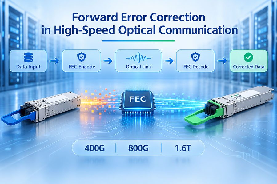
| Pre-FEC BER | Bit error rate before error correction | Shows signal quality before FEC processing. |
| Post-FEC Performance | Errors remaining after FEC processing | Helps assess whether the link is operating within acceptable limits. |
| Module Temperature | Operating temperature of the transceiver | Helps identify thermal issues and cooling problems. |
Available diagnostic parameters vary by module and host implementation. Engineers should establish baseline values during commissioning and monitor changes over time rather than relying on a single measurement.
11. Typical 400ZR DCI Applications
400ZR is particularly relevant where high-capacity Ethernet connections are required between separate facilities and the network distance exceeds the practical range of conventional short-reach optics.
Cloud data center interconnection: Connects distributed data center facilities supporting cloud computing, storage and application services.
Enterprise data center links: Provides high-capacity connectivity between primary and secondary data center locations.
Content delivery infrastructure: Supports high-volume traffic exchange between regional infrastructure sites.
AI infrastructure connectivity: Connects distributed computing and storage facilities where high-capacity data movement is required.
Carrier and peering networks: Supports 400G Ethernet transport across suitable metropolitan DWDM infrastructure.
The best application is generally a relatively short, high-capacity coherent link with a suitable point-to-point optical path. Longer or more complex network topologies may require extended coherent technologies or a different transport architecture.
12. C-LIGHT 400G Optical Connectivity Solutions
Building a high-capacity DCI network involves more than selecting a single optical module. Host interfaces, short-reach connections, fiber infrastructure and DWDM transport components must work together as part of a complete network architecture.
400G QSFP-DD Optical Transceivers
The C-LIGHT 400G QSFP-DD product family supports high-speed Ethernet connectivity for data center and network infrastructure applications. Depending on the selected optical specification, 400G client-side modules can serve switch-to-switch, server-to-network and other high-bandwidth connections.
For DCI projects, the exact optical interface must be selected according to the link architecture. Conventional 400G PAM4 modules and 400ZR coherent modules serve different optical applications and should not be treated as interchangeable.
800G Optical Transceiver Platforms
As network capacity requirements continue to increase, 800G interfaces are becoming important in next-generation data center architectures. C-LIGHT provides 800G QSFP-DD and 800G OSFP product families for high-density data center connectivity.
These product families are relevant to the client-side and intra-data-center connectivity ecosystem. Their specific reach and interface specifications should be matched to the intended application.
For projects requiring 400ZR coherent DCO modules, compatibility and availability should be confirmed against the exact host platform, optical line system and required transmission distance. Product selection should be based on verified datasheets rather than data-rate or form-factor similarity alone.
13. How to Select a 400ZR Solution
A reliable 400ZR deployment begins with a clear understanding of the network path and equipment environment. The following sequence provides a practical engineering approach.
Define the link requirements: Confirm the required 400GbE capacity, distance, number of wavelengths and expected traffic growth.
Identify the host equipment: Record the switch or router model, supported port type, software version and module power limitations.
Evaluate the fiber path: Check fiber type, route length, connector losses, splice losses and available optical infrastructure.
Plan the DWDM channels: Confirm wavelength grid, MUX/DEMUX characteristics and channel allocation.
Calculate optical performance: Evaluate link loss, OSNR, amplifier requirements and operating margin.
Validate interoperability: Confirm module compliance, host support and line-system compatibility.
Test before deployment: Verify link establishment, Ethernet performance, diagnostic readings and stability under operating conditions.
This process helps prevent common deployment problems such as unsupported modules, insufficient OSNR, excessive optical loss, thermal limitations and mismatched DWDM channel configurations.
14. Conclusion
400ZR is an important technology for high-capacity data center interconnects. By integrating coherent optical transmission into compact pluggable modules, it enables 400GbE traffic to travel over suitable DWDM links while simplifying the equipment architecture at the network edge.
Its value is especially clear in point-to-point metropolitan DCI applications where operators need high bandwidth, optical interoperability and efficient use of existing fiber infrastructure. Successful deployment, however, depends on more than the nominal transmission distance. Host compatibility, optical link budget, OSNR, DWDM channel planning, power and thermal performance must all be considered.
As data center networks evolve toward 800G and 1.6T connectivity, 400ZR remains an important reference point in the development of coherent pluggable optics and scalable optical transport architectures.
Build Reliable 400G Optical Networks
Choosing the right optical connectivity requires careful consideration of data rate, transmission distance, platform compatibility and network architecture. Contact C-LIGHT for product information and technical support for your optical networking project.
Contact C-LIGHT >

 >
 >
 >
 >
 >
 >
 >