TEL:+86 132 6656 7067





100GBASE-LR4 and 100G OTU4 are associated with 100G optical transmission, but they belong to different technical specifications. 100GBASE-LR4 is an IEEE Ethernet physical-layer interface using four LAN-WDM wavelengths over duplex single-mode fiber. OTU4 is an ITU-T Optical Transport Network signal format with a nominal line rate of approximately 111.81 Gbit/s.
The distinction is between an Ethernet optical PHY and an OTN transport signal. A compatible LR4 optical module can also be used in certain OTU4 implementations through the OTL4.4 interface, making electrical-interface compatibility and equipment configuration important considerations.
1. 100GBASE-LR4 and OTU4: Two Different Specifications
100GBASE-LR4 is defined by IEEE 802.3 and specifies the optical physical-layer characteristics for 100 Gigabit Ethernet transmission over single-mode fiber. It uses four wavelengths around 1310 nm, with each optical lane carrying approximately 25.78 Gbit/s. The four wavelengths are multiplexed onto one transmit fiber and demultiplexed at the receiving end.
OTU4, or Optical Transport Unit 4, is defined by ITU-T G.709. It belongs to the OTN hierarchy and provides a structured transport frame for carrying client signals such as 100GbE. Its line signal includes transport overhead and forward error correction information in addition to the client payload.
| Technical Aspect | 100GBASE-LR4 | 100G OTU4 |
|---|---|---|
| Standard | IEEE 802.3 | ITU-T G.709 |
| Technology layer | Ethernet physical layer | Optical transport layer |
| Nominal data rate | 100G Ethernet | Approximately 111.81 Gbit/s line rate |
| Optical architecture | Four LAN-WDM optical lanes | Depends on the OTU4 optical interface implementation |
| Typical wavelength range | Four wavelengths around 1310 nm | May use compatible LAN-WDM optics or other defined optical line interfaces |
| Fiber type | Duplex single-mode fiber | Depends on the optical application and line interface |
| Typical reach | Up to 10 km | Depends on the optical interface and transport system |
| Primary function | Ethernet frame transmission | OTN framing, transport, monitoring and FEC |
The two specifications are therefore not direct alternatives. An Ethernet signal can be carried through an OTN network, and compatible optical components may be shared between the two interface applications.
2. Optical Wavelengths and Transmission Architecture of 100GBASE-LR4
100GBASE-LR4 uses four LAN-WDM wavelengths within the 1310 nm region. Each wavelength carries one approximately 25.78 Gbit/s optical channel. A wavelength multiplexer combines the four channels for transmission over a single-mode fiber, while a demultiplexer separates them at the receiver.
100GBASE-LR4 Optical Transmission
The four nominal center wavelengths are:
| Optical Lane | Nominal Wavelength | Function |
|---|---|---|
| Lane 1 | 1295.56 nm | First 25G-class optical channel |
| Lane 2 | 1300.05 nm | Second 25G-class optical channel |
| Lane 3 | 1304.58 nm | Third 25G-class optical channel |
| Lane 4 | 1309.14 nm | Fourth 25G-class optical channel |
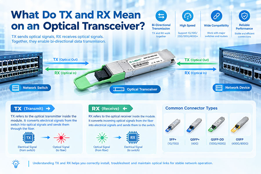
The optical interface is designed for duplex single-mode fiber, normally using an LC duplex connector on common QSFP28 implementations. One fiber carries the combined transmit signal and the other carries the receive signal.
For the standardized LR4 application, the specified reach is up to 10 km over suitable single-mode fiber. Actual link performance must still meet the relevant channel insertion-loss, connector, fiber and optical power requirements.
3. OTU4 Line Rate and OTN Frame Structure
OTU4 operates at approximately 111.81 Gbit/s. This is higher than the 100GbE client rate because the OTN signal includes additional transport information.
Its frame structure consists of three principal layers: OPU4, ODU4 and OTU4.
OPU4: Provides the payload structure and client-signal adaptation functions.
ODU4: Provides the digital path-layer container, including path overhead and monitoring functions.
OTU4: Adds transport-section overhead and FEC information for transmission across the optical transport section.
OTU4 Signal Processing Structure
A 100GbE client signal can be mapped into the OTN structure and transported through an OTU4 network. The transport layer provides functions beyond the optical transmission itself, including path monitoring, fault indications and error correction.
This is the main difference from a standalone 100GBASE-LR4 Ethernet link. LR4 defines the optical PHY used to transmit Ethernet data, while OTU4 defines the transport signal structure used to carry client traffic across an OTN network.
4. The Important Connection: OTL4.4 and LR4 Optical Module Reuse
Although 100GBASE-LR4 and OTU4 are different specifications, they have an important point of compatibility. ITU-T defines OTL4.4 as an OTU4 optical interface arrangement that can reuse suitable 100GBASE-LR4 optical modules.
This approach allows an optical module originally developed for a 100G Ethernet LR4 application to serve as the optical interface for an OTU4 signal, provided that the equipment implements the required OTL4.4 electrical interface and meets the relevant optical specifications.
Compatible LR4 Optical Module Used in an OTL4.4 Interface
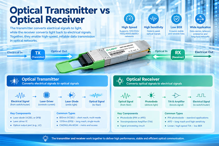
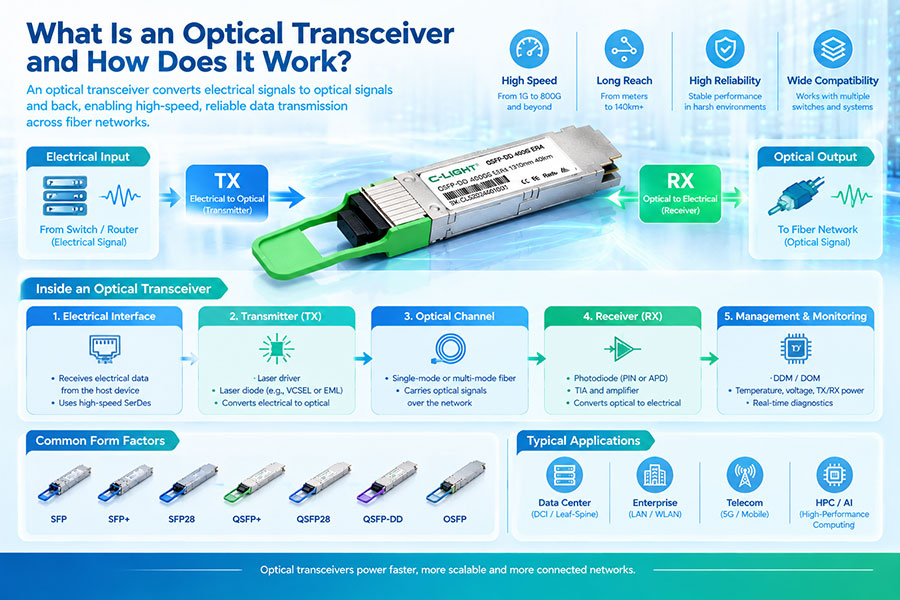
The optical module handles the four-channel optical transmission and reception. The host equipment handles the electrical interface and the OTN processing required to generate or recover the OTU4 signal.
This is an important distinction when evaluating module compatibility. Sharing the same optical module does not mean that every LR4 Ethernet port can operate as an OTU4 port. The host-side electrical interface, signal mapping, timing and equipment configuration must support the intended OTN application.
OTL4.4 is not simply another name for 100GBASE-LR4. It is an OTN optical interface arrangement that enables reuse of compatible LR4-class optical hardware. The complete interface includes both the optical module requirements and the host-side electrical signal requirements.
5. FEC and Error Performance: LR4 vs. OTU4
Forward Error Correction is another important difference between the two technologies.
100GBASE-LR4 is designed as an Ethernet optical PHY with specified error performance. Its traditional LR4 implementation does not require host-side FEC for the standard 10 km application. The LAN-WDM wavelength arrangement and optical performance specifications are designed to achieve the required Ethernet bit error performance under compliant link conditions.
OTU4, on the other hand, includes FEC as part of its transport signal architecture. The receiving equipment uses the corresponding FEC processing to detect and correct errors within the correction capability of the selected scheme.
| Parameter | 100GBASE-LR4 | OTU4 |
|---|---|---|
| FEC role | Not required as host FEC for the standard LR4 10 km application | Transport-layer FEC is part of the OTU4 signal structure |
| Error monitoring | Ethernet PHY and MAC-related error performance | OTN transport and path performance monitoring |
| Corrected error information | Depends on the host and PHY diagnostic implementation | Available through the transport equipment's FEC monitoring |
| Primary objective | Meet Ethernet link error requirements | Improve transport robustness and provide transport-layer error visibility |
FEC capabilities must be evaluated at the correct interface layer. An LR4 optical module's Ethernet error-performance specification should not be confused with the FEC function implemented by an OTU4 transponder or transport card.
6. Can a 100GBASE-LR4 Transceiver Be Used for OTU4?
Yes, compatible 100GBASE-LR4 optical modules can be used in certain OTU4 implementations through the OTL4.4 interface. This reuse is part of the OTN interface design and can reduce the need for a separate optical module type.
However, successful operation depends on several conditions:
OTL4.4 support: The OTN equipment must support the relevant OTL4.4 interface configuration.
Electrical interface compatibility: The host-side electrical signaling must match the module and equipment implementation.
Optical specifications: The LR4 module must meet the required wavelength, transmit power, receiver sensitivity and other optical parameters.
Signal processing: The host must implement OTU4 framing, mapping, FEC and associated monitoring functions.
Module qualification: The equipment vendor must support or qualify the specific module model and firmware configuration.
A standard QSFP28 LR4 module inserted into an ordinary Ethernet switch port does not automatically become an OTU4 interface. OTU4 operation requires the correct OTN-capable host equipment and electrical interface.
7. Typical Applications of 100GBASE-LR4 and OTU4
100GBASE-LR4 is widely used for direct 100G Ethernet connections between network devices. Its 10 km single-mode fiber reach makes it suitable for campus networks, data center interconnections and enterprise aggregation links.
OTU4 is more closely associated with managed optical transport infrastructure. It is used in systems that require OTN framing, transport-layer monitoring, FEC and service aggregation across metro or backbone networks.
| Application | 100GBASE-LR4 | OTU4 |
|---|---|---|
| Enterprise Ethernet connections | Directly suitable | Usually unnecessary for a simple Ethernet link |
| Data center Ethernet switching | Suitable for supported 10 km links | Used when an OTN transport layer is part of the architecture |
| Metro optical transport | Can provide client or compatible optical interfaces | Provides managed 100G-class transport |
| DWDM transport | Can be used as a client interface or in compatible OTL4.4 arrangements | Provides the OTN signal carried through the transport system |
| Carrier backbone | May serve as a client-facing interface | Suitable for 100G-class OTN transport paths |
| Direct router-to-router Ethernet | Suitable when both ports support LR4 | Requires OTN-capable equipment at the relevant interfaces |
In a typical carrier network, a router may generate 100GbE traffic using an LR4 optical interface. An OTN transport system can map that client traffic into an ODU4 container and carry it over an OTU4 line interface. This creates a transport path with monitoring and FEC capabilities beyond the original Ethernet connection.
8. Key Parameters to Check When Selecting an LR4 or OTU4 Interface
Choosing between LR4 and OTU4 requires identifying the function of the port before selecting the optical module. The following parameters should be checked during network design and equipment qualification.
| Selection Parameter | What to Verify |
|---|---|
| Port protocol | 100GbE, OTU4 or OTL4.4 support |
| Host electrical interface | CAUI-4, OTL4.4 or the specific supported host interface |
| Optical wavelengths | Four LAN-WDM channels around 1310 nm for LR4-compatible applications |
| Fiber type | Duplex single-mode fiber and applicable channel specifications |
| Transmission distance | Up to 10 km for standard 100GBASE-LR4 application conditions |
| FEC configuration | Host Ethernet FEC requirements or OTU4 transport FEC support |
| Connector | LC duplex or the connector specified by the module design |
| Form factor | QSFP28, CFP or another supported module format |
| Management | DDM/DOM support and host equipment compatibility |
For optical link engineering, transmitter output power, receiver sensitivity, channel insertion loss and fiber attenuation should be checked against the applicable module specification. For OTN systems, the electrical interface and transport configuration are equally important.
9. Common Compatibility and Link Issues
Problems involving LR4 and OTU4 interfaces often arise when the optical module is selected based only on its 100G rate or physical form factor. The following checks help identify common causes.
| Problem | Possible Cause | Recommended Verification |
|---|---|---|
| LR4 module is not recognized | Unsupported module coding, firmware or hardware qualification | Check host compatibility and module identification information |
| Optical link is up but OTU4 is unavailable | Host port is configured for Ethernet rather than OTN | Verify OTL4.4 support and OTU4 port configuration |
| Electrical signal mismatch | Different host electrical interface or signal mapping | Check the equipment's electrical interface specification |
| High bit error rate | Fiber loss, dirty connectors, optical power outside limits or signal impairment | Inspect optical power, fiber condition and error statistics |
| FEC alarm or uncorrectable errors | Incorrect FEC configuration or degraded optical transport signal | Verify the OTN FEC mode and transport link performance |
| Intermittent link instability | Temperature variation, unstable optical output or host issues | Review module diagnostics, equipment alarms and operating conditions |
When diagnosing an OTU4 link, engineers should distinguish between an optical-layer fault and an OTN framing or electrical-interface fault. A module may transmit and receive optical signals correctly while the host equipment still fails to establish the required OTU4 transport signal.
10. Conclusion: LR4 Defines the Optical PHY, OTU4 Defines the Transport Signal
100GBASE-LR4 and 100G OTU4 are closely related in 100G optical networking, but they serve different technical functions. LR4 defines a four-wavelength Ethernet optical interface for transmission over up to 10 km of single-mode fiber. OTU4 defines the OTN transport signal, including its approximately 111.81 Gbit/s line rate, framing, overhead and FEC.
The OTL4.4 interface provides an important connection between these technologies by allowing compatible LR4 optical modules to be reused in OTU4 equipment. This does not make every LR4 Ethernet port OTU4-compatible; the host electrical interface, OTN processing and equipment qualification must also match.
For network engineers, the correct selection depends on whether the requirement is a direct 100GbE optical connection or a managed OTN transport interface. Verifying the complete electrical and optical specifications is essential for reliable interoperability.
100G Optical Connectivity for Ethernet and Transport Networks
C-LIGHT provides 100G optical transceiver solutions for enterprise networking, data center connectivity and optical transport applications. Module selection should be based on the required Ethernet or OTN interface, optical reach and host equipment compatibility.
Need a compatible 100G optical interface?
Contact C-LIGHT for optical module specifications, host compatibility evaluation and 100G Ethernet or optical transport connectivity requirements.
 >

 >
 >
 >
 >
 >
 >
 >