TEL:+86 132 6656 7067




800G optical networking represents a major increase in data center bandwidth, but the most important change is not simply the increase from 400G to 800G. The electrical and optical signaling rates required to reach 800G also create significant challenges for signal integrity, power consumption, packaging and transmission distance.
PAM4 is one of the key technologies that makes high-speed 800G transmission practical. Instead of using two signal levels like NRZ, PAM4 uses four signal levels and carries two bits per symbol. This allows a higher bit rate to be achieved without doubling the symbol rate.
However, 800G does not inherently require PAM4 in every optical architecture. Many modern 800G Ethernet implementations use PAM4, while other 800G systems can use different modulation or transmission architectures. The use of PAM4 depends on the interface design, lane rate, optical technology and application.
1. What Is PAM4?
PAM4 stands for Pulse Amplitude Modulation with 4 levels.
Instead of transmitting information with only two amplitude levels, PAM4 uses four distinct signal levels.
Each symbol can therefore represent one of four possible states.
2. How Many Bits Does PAM4 Carry per Symbol?
PAM4 carries 2 bits per symbol.
The four amplitude levels can represent the four possible combinations of two binary bits: 00, 01, 10 and 11.
This doubles the number of bits carried by each symbol compared with NRZ, which carries 1 bit per symbol.
3. What Is NRZ?
NRZ stands for Non-Return-to-Zero.
NRZ uses two primary signal levels to represent binary information.
Because there are two levels, one symbol represents one bit.
4. PAM4 vs NRZ
| Feature | NRZ | PAM4 |
|---|---|---|
| Signal Levels | 2 | 4 |
| Bits per Symbol | 1 | 2 |
| Data Efficiency | 1 bit/symbol | 2 bits/symbol |
| Required Baud Rate | Higher for the same bit rate | Lower for the same bit rate |
| Eye Openings | Larger | Smaller |
| Noise Margin | Higher | Lower |
| Signal Processing | Relatively simpler | More demanding |
5. Why Was NRZ Not Enough for 800G?
The key limitation of NRZ is that it carries only one bit per symbol.
To increase the data rate with NRZ, the symbol rate must increase proportionally.
At very high speeds, increasing the baud rate creates greater challenges for electrical channels, PCB traces, connectors, drivers, receivers and optical components.
6. Why Does PAM4 Help 800G?
PAM4 doubles the number of bits transmitted per symbol.
For the same symbol rate, PAM4 can theoretically carry twice as many bits as NRZ.
This makes it possible to reach much higher aggregate data rates without simply doubling the baud rate.
7. The Basic Mathematical Principle
For a simplified signaling system, the relationship between bit rate and symbol rate can be expressed as:
Bit Rate = Symbol Rate × Bits per Symbol
For NRZ:
Bit Rate = Symbol Rate × 1
For PAM4:
Bit Rate = Symbol Rate × 2
This is the fundamental reason PAM4 is attractive for 800G and other high-speed interfaces.
8. Example of PAM4 Efficiency
Suppose an optical lane operates at approximately 53 GBd.
An NRZ signal at that symbol rate carries approximately 53 Gbit/s before accounting for encoding and implementation overhead.
A PAM4 signal at the same symbol rate can theoretically carry approximately 106 Gbit/s before overhead.
This is why PAM4 became closely associated with 100G-class electrical and optical lanes.
9. 800G and 100G-Class Lanes
One common approach to 800G Ethernet uses multiple approximately 100G-class electrical lanes.
Using PAM4 allows these lanes to operate at around 100Gbit/s class data rates without requiring NRZ signaling at roughly 100 GBd.
The exact lane rate depends on the specific Ethernet implementation and physical-layer architecture.
10. 800G Does Not Mean One 800G Signal
800G is an aggregate interface speed rather than a single optical waveform.
An 800G interface is normally divided into multiple electrical and optical lanes.
The lane count and lane rate depend on the module architecture, host interface and optical standard.
11. 800G and Lane Multiplexing
High-speed transceivers divide the aggregate data rate into multiple parallel lanes.
For example, an architecture may use eight electrical lanes or a different number of optical lanes depending on the optical design.
PAM4 allows each lane to carry more data without requiring the same proportional increase in baud rate.
12. 800G Electrical Lanes
Many 800G Ethernet architectures use high-speed electrical lanes in the approximately 100G-per-lane class.
PAM4 enables these electrical lanes to carry around twice the information per symbol compared with NRZ.
This helps maintain the electrical signaling requirements within a more manageable range.
13. 800G Optical Lanes
The optical lane structure does not always match the electrical lane structure.
An optical transceiver can use a gearbox, DSP or lane conversion function to adapt between the host electrical interface and the optical architecture.
For example, some WDM designs use fewer optical lanes by increasing the amount of data carried by each optical channel.
14. 800G PAM4 and WDM
WDM allows multiple optical wavelengths to share the same fiber.
With PAM4, each wavelength can carry a high data rate while multiple wavelengths together create the aggregate 800G capacity.
This architecture is useful for high-density single-mode optical transceivers.
15. 800G PAM4 and Parallel Optics
800G can also use parallel optical architectures in which multiple optical lanes are carried over multiple fibers.
Each optical lane can use PAM4, allowing the total data rate to be distributed across multiple channels.
The exact lane configuration depends on the transceiver design.
16. 800G PAM4 and Fiber Count
PAM4 does not determine the number of fibers used by an optical module.
An 800G module can use parallel single-mode fibers, multimode fibers or WDM over a smaller number of fibers depending on the architecture.
Fiber count is determined by the optical interface design rather than the modulation format alone.
17. Why Not Simply Increase NRZ Speed?
Higher NRZ baud rates become increasingly difficult because the electrical channel must preserve higher-frequency signal content.
PCB traces, connectors, packages and cables introduce more loss and distortion at higher frequencies.
Moving from NRZ to PAM4 increases the number of bits transmitted per symbol and reduces the required symbol rate for a given data throughput.
18. PAM4 and Electrical Channel Loss
Electrical insertion loss generally increases with frequency.
Operating at a lower symbol rate for a given data rate can reduce some of the high-frequency requirements on the channel.
PAM4 therefore helps make very high aggregate data rates more practical within available electrical channel technologies.
19. PAM4 and PCB Design
High-speed PCB traces must control insertion loss, reflections, crosstalk and impedance discontinuities.
As signaling rates increase, these impairments become more difficult to manage.
PAM4 can reduce the required baud rate compared with an equivalent NRZ implementation, although its smaller signal margins create new challenges.
20. PAM4 and Connector Performance
High-speed connectors introduce insertion loss and reflections into the signal path.
At higher baud rates, these effects become more significant.
PAM4 helps manage the baud-rate requirement but also requires tighter control of amplitude and linearity because the receiver must distinguish four levels rather than two.
21. PAM4 and Signal-to-Noise Ratio
One of the major trade-offs of PAM4 is reduced vertical eye opening.
The four signal levels occupy the available voltage range, leaving less separation between adjacent levels than a two-level NRZ signal.
This makes PAM4 more sensitive to noise and distortion.
22. Why Does PAM4 Have Smaller Eye Openings?
A PAM4 waveform contains four levels distributed across the signal amplitude range.
This produces three decision thresholds and three vertical eye regions.
Because the same overall voltage range is divided into more levels, each individual eye opening is smaller than the single NRZ eye.
23. PAM4 and Error Probability
The smaller eye openings of PAM4 make the receiver more sensitive to amplitude noise, distortion and other impairments.
As a result, achieving a target raw bit-error rate becomes more difficult than with a comparable NRZ system.
This is one reason high-speed PAM4 systems often rely on stronger signal processing and FEC.
24. PAM4 and FEC
FEC stands for Forward Error Correction.
FEC adds redundant information that allows the receiver to detect and correct certain transmission errors.
FEC is an important technology in many high-speed PAM4 Ethernet systems because it provides additional link margin against raw transmission errors.
25. Why Does 800G Need FEC?
PAM4 provides higher spectral efficiency but creates smaller signal margins.
At the same time, 800G operates at very high electrical and optical speeds.
FEC can therefore be used to reduce the effective post-correction error rate and enable the required link performance.
26. Pre-FEC BER vs Post-FEC BER
Pre-FEC BER describes the error rate before error correction.
Post-FEC BER describes the residual error rate after the FEC decoder has processed the data.
A PAM4 link can therefore operate with a non-zero pre-FEC error rate while achieving a much lower post-FEC error rate when the FEC system has sufficient correction capability.
27. PAM4 and DSP
DSP stands for Digital Signal Processor.
A high-speed optical DSP can perform equalization, clock recovery, signal processing and FEC-related functions depending on the device architecture.
DSP technology is an important part of many 800G PAM4 transceiver designs.
28. Why Is DSP Important for 800G PAM4?
PAM4 systems have tighter signal margins and must distinguish four amplitude levels.
DSP can compensate for electrical channel loss, inter-symbol interference and other signal impairments.
This improves the ability of the receiver to recover the transmitted data.
29. PAM4 Equalization
Equalization compensates for frequency-dependent channel loss and waveform distortion.
High-speed 800G systems can use transmitter-side and receiver-side equalization techniques.
The exact implementation depends on the DSP, SerDes and optical module design.
30. PAM4 and CTLE
CTLE stands for Continuous-Time Linear Equalizer.
It emphasizes frequency components that have been attenuated by the transmission channel.
CTLE can be part of the signal-conditioning chain used with high-speed PAM4 SerDes.
31. PAM4 and FFE
FFE stands for Feed-Forward Equalizer.
FFE applies weighted signal taps to compensate for channel distortion.
Both transmit-side and receive-side FFE can be used in high-speed PAM4 systems.
32. PAM4 and DFE
DFE stands for Decision Feedback Equalizer.
DFE uses previous symbol decisions to compensate for inter-symbol interference.
It can be useful in high-speed receivers where channel distortion makes signal decisions more difficult.
33. PAM4 and TDECQ
TDECQ stands for Transmitter and Dispersion Eye Closure for PAM4.
It is an important measurement used to evaluate PAM4 transmitter performance.
Unlike a simple optical power measurement, TDECQ evaluates the quality of the transmitted PAM4 waveform after a reference equalization process.
34. PAM4 and OMA
OMA, or Optical Modulation Amplitude, measures the modulation amplitude of an optical signal.
For PAM4, multiple definitions can be used depending on the specification, including outer-level optical modulation amplitude.
OMA should not be confused with average optical power.
35. PAM4 and Average Optical Power
Average optical power is the average optical energy of the transmitted waveform.
PAM4 modulation performance is related to the spacing and relationship between optical levels rather than average power alone.
A module can therefore meet an average launch-power requirement while still failing waveform-quality requirements.
36. PAM4 and Extinction Ratio
Extinction ratio describes the relationship between optical power levels for a modulated transmitter.
In PAM4 systems, the waveform contains more than two levels, so additional measurements such as TDECQ and OMA are important for evaluating signal quality.
37. PAM4 and Linear Drivers
Linear drivers preserve the multi-level characteristics of the PAM4 signal while driving the optical transmitter.
In some optical architectures, a linear driver can be used without a conventional retiming DSP inside the module.
This approach is particularly relevant to LPO architectures.
38. PAM4 and Optical Modulators
The electrical PAM4 waveform can drive different optical transmitter technologies.
Depending on the architecture, the transmitter may use a directly modulated laser, an electro-absorption modulated laser, a silicon photonics modulator or another optical device.
39. PAM4 and EML
EML combines a semiconductor laser with an electro-absorption modulator.
EML is commonly used in high-speed single-mode optical systems and can support PAM4 transmission when the device and driver are designed for the required signaling rate.
EML and PAM4 describe different aspects of a transmitter: EML is the optical transmitter technology, while PAM4 is the modulation format.
40. PAM4 and VCSEL
VCSEL technology is widely used for short-reach optical transmission.
Modern VCSEL-based systems can support high-speed multi-level signaling when the VCSEL, driver and optical link are designed for the required performance.
Therefore, PAM4 is not limited to one type of laser technology.
41. PAM4 and Silicon Photonics
Silicon photonics can use integrated optical modulators to convert high-speed electrical signals into optical signals.
PAM4 electrical signals can be applied to suitable silicon photonics transmitter architectures.
This makes silicon photonics another potential optical platform for high-speed PAM4 modules.
42. Why 800G Uses PAM4 Instead of Higher-Speed NRZ
| Factor | Higher-Speed NRZ | PAM4 |
|---|---|---|
| Bits per Symbol | 1 | 2 |
| Baud Requirement | Higher | Lower for the same bit rate |
| Signal Levels | 2 | 4 |
| Eye Opening | Larger | Smaller |
| Noise Margin | Higher | Lower |
| DSP Requirement | Generally simpler | More demanding |
| FEC Requirement | Lower in many implementations | More important in many implementations |
43. PAM4 and Spectral Efficiency
Spectral efficiency describes how many bits can be transmitted for a given amount of occupied bandwidth.
By carrying two bits per symbol, PAM4 increases the information transmitted per symbol compared with NRZ.
This helps increase bandwidth without requiring the same proportional increase in signal bandwidth.
44. Is PAM4 More Bandwidth Efficient Than NRZ?
Yes, in terms of bits transmitted per symbol, PAM4 is twice as efficient as NRZ.
However, this does not mean PAM4 automatically provides twice the practical system capacity in every network.
Driver limitations, optical bandwidth, equalization, FEC and implementation overhead all affect the final result.
45. PAM4 and 800G Optical Module Size
PAM4 can help maintain manageable lane baud rates while increasing total module throughput.
This can allow high-speed modules to remain within practical form-factor and packaging constraints.
However, the module still requires multiple lanes, high-speed drivers and substantial thermal management.
46. PAM4 and 800G Power Consumption
PAM4 itself does not automatically make an 800G optical module low power.
The signal-processing requirements, DSP, driver, laser, TIA and cooling system all contribute to module power.
PAM4 can reduce the baud rate required for a given bit rate, but it also introduces more demanding signal-processing requirements.
47. PAM4 and 800G Thermal Design
High-speed electrical and optical components generate significant heat.
DSPs, drivers, lasers and optical receivers all contribute to the thermal load of an 800G module.
Thermal design is therefore a major consideration when implementing PAM4 at high aggregate data rates.
48. 800G PAM4 and DSP-Based Modules
Many 800G optical modules use DSP-based architectures.
The DSP can provide signal equalization, lane processing, clock recovery and FEC-related functions.
This architecture improves tolerance to challenging electrical and optical channels but increases module power and complexity.
49. 800G PAM4 and LPO
LPO stands for Linear Pluggable Optics.
LPO removes the conventional high-speed DSP from many optical modules and uses a more linear signal path.
PAM4 remains the signaling format, but more of the signal-conditioning responsibility moves toward the host SerDes and electrical system.
50. DSP-Based 800G vs LPO 800G
| Feature | DSP-Based 800G | LPO 800G |
|---|---|---|
| Modulation | PAM4 in many implementations | PAM4 in many implementations |
| Module DSP | Yes | Typically no conventional DSP |
| Module Power | Generally higher | Potentially lower |
| Latency | Higher | Lower |
| Host Channel Requirement | More tolerant | More demanding |
| Signal Conditioning | More inside the module | More dependent on host system |
51. Why PAM4 Is Important for 800G AI Data Centers
AI data centers require very large amounts of east-west traffic between GPUs, network adapters and switches.
Increasing interface speed allows more data to move through each physical network connection.
PAM4 helps enable these higher-speed electrical and optical interfaces by increasing bits per symbol without requiring a proportional increase in baud rate.
52. 800G PAM4 and AI Scale-Out Networking
AI scale-out networks use high-bandwidth connections between servers and switches.
800G interfaces can provide higher capacity per port than 400G interfaces, while PAM4 makes the required lane rates more practical.
This is one reason PAM4 is closely associated with modern AI data center networking.
53. 800G PAM4 and GPU Networks
GPU clusters generate large volumes of network traffic during distributed training and inference.
Higher-speed optical ports can increase the bandwidth available between AI servers and network switches.
PAM4 allows these ports to achieve high aggregate throughput with manageable lane baud rates.
54. 800G PAM4 and Data Center Switches
Data center switches need to support very high aggregate switching capacity.
Using PAM4-based high-speed SerDes allows each electrical lane to operate at a higher data rate without requiring an equivalent increase in symbol rate compared with NRZ.
This supports higher-density switch architectures.
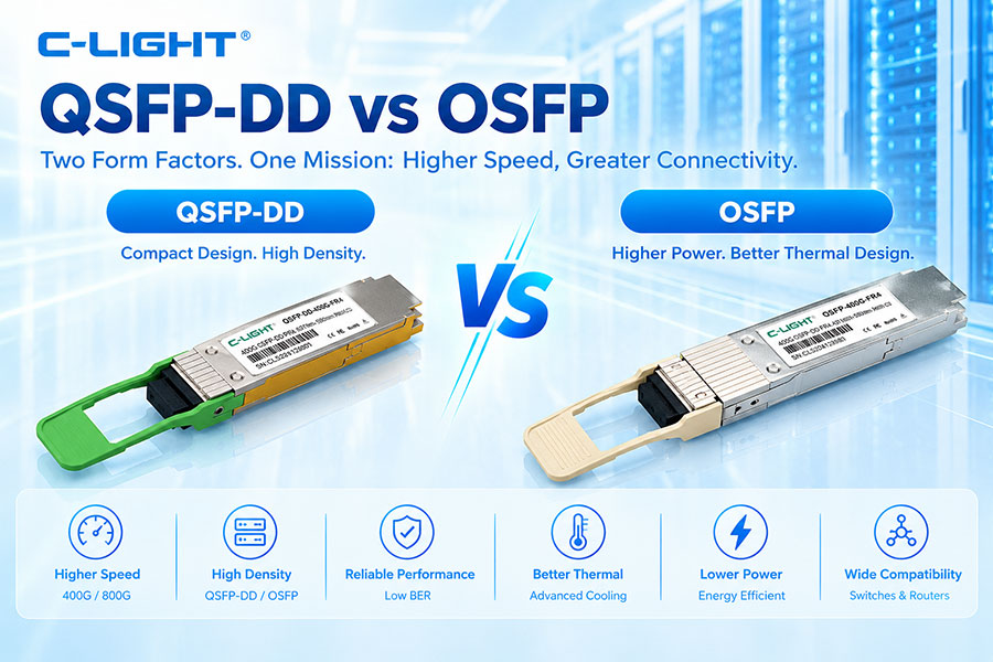
55. 800G PAM4 and OSFP
OSFP is a high-speed optical module form factor used for many 800G applications.
An 800G OSFP transceiver can use PAM4 electrical and optical signaling depending on its architecture.
The OSFP form factor itself does not define the modulation format; the specific optical and electrical implementation does.
56. 800G PAM4 and QSFP-DD
QSFP-DD is another high-density pluggable optical form factor used for high-speed networking.
800G QSFP-DD modules can also use PAM4-based electrical and optical architectures.
Again, PAM4 is a signaling technology rather than a mechanical form factor.
57. 800G and PAM4 Electrical Signaling
The electrical interface between a switch ASIC and optical module is one of the most important places where PAM4 is used.
High-speed host SerDes can use PAM4 to transmit more information per symbol through the electrical channel.
This makes the electrical path one of the major areas where the benefits of PAM4 become apparent.
58. 800G and PAM4 Optical Signaling
The optical transmitter can also use PAM4 modulation.
The electrical PAM4 signal is converted into corresponding optical amplitude levels by the transmitter architecture.
The receiver detects those levels and reconstructs the original digital information.
59. Does Every 800G Optical Module Use PAM4?
No.
PAM4 is widely used in modern 800G Ethernet and data center optical implementations, but "800G" describes aggregate capacity rather than one mandatory modulation format.
Other optical technologies, including coherent modulation, can also be used in 800G systems for different applications.
60. 800G PAM4 vs 800G Coherent
| Feature | 800G PAM4 | 800G Coherent |
|---|---|---|
| Typical Environment | Data center Ethernet | Longer-reach optical transport and DCI applications |
| Detection | Typically direct detection | Coherent detection |
| Amplitude Levels | Four electrical/optical levels | Amplitude and phase information |
| DSP | Common in high-speed implementations | Central to coherent operation |
| Reach | Typically short to moderate depending on implementation | Can support much longer optical distances |
| Complexity | Lower than coherent systems | Higher |
61. 800G PAM4 vs 800G NRZ
An 800G NRZ architecture would require substantially higher symbol rates or more parallel lanes to reach the same aggregate throughput.
PAM4 provides a more practical balance by carrying two bits per symbol.
This does not mean that NRZ is fundamentally unsuitable for all high-speed systems, but it becomes increasingly difficult to scale to very high aggregate bandwidth.
62. PAM4 and 400G
PAM4 is already widely associated with 400G Ethernet.
For many 400G architectures, PAM4 allows approximately 100G-class signaling lanes to be implemented using about 50 GBd-class symbol rates.
The transition to 800G extends this concept to a larger aggregate number of lanes and higher per-lane performance.
63. PAM4 and the Transition from 400G to 800G
| Generation | Typical Signaling Approach | Main Scaling Challenge |
|---|---|---|
| 100G | NRZ or PAM4 depending on architecture | Increasing lane speed |
| 200G | PAM4 increasingly important | Higher per-lane speed |
| 400G | PAM4 widely used | Multiple high-speed lanes |
| 800G | PAM4 widely used in Ethernet implementations | Higher aggregate bandwidth and signal integrity |
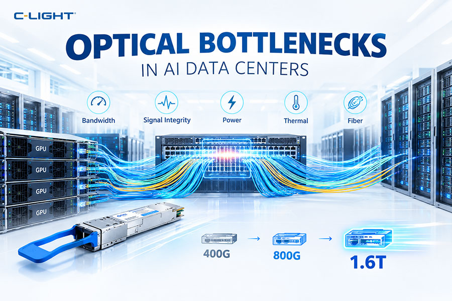
| 1.6T | Advanced PAM4 architectures and other approaches | Very high lane rate and thermal constraints |
64. Why PAM4 Continues Into 1.6T
PAM4 provides a fundamental 2-bit-per-symbol efficiency advantage compared with NRZ.
As data rates continue to increase, simply returning to NRZ would require even greater symbol rates or many more lanes.
Therefore, higher-performance PAM4 implementations remain an important part of the roadmap toward 1.6T and beyond.
65. The Trade-Off of PAM4
PAM4 solves one problem while creating another.
It reduces the symbol rate required for a given bit rate, but it reduces the vertical eye opening and increases sensitivity to noise and distortion.
Modern high-speed systems address this trade-off using equalization, DSP, FEC, improved components and better channel design.
66. PAM4 and Channel Design
Because PAM4 has smaller signal margins, every part of the signal path becomes important.
Package design, PCB materials, connectors, cables, drivers, optical devices and receivers must all maintain sufficient signal quality.
This makes system-level channel design essential for 800G implementation.
67. PAM4 and Packaging
High-speed package interconnects introduce parasitic capacitance, inductance and loss.
At 800G, these effects can significantly influence signal quality.
PAM4-compatible packaging therefore requires careful control of high-speed electrical paths.
68. PAM4 and Crosstalk
Crosstalk occurs when signals on adjacent channels interfere with each other.
Because PAM4 has smaller eye openings, crosstalk can have a more visible effect on signal quality.
High-density 800G modules therefore require careful control of channel spacing, routing and shielding.
69. PAM4 and Reflections
Impedance discontinuities can create reflections that distort the received waveform.
At high signaling rates, even small discontinuities can reduce the available eye margin.
PAM4 systems require tight impedance control across the complete electrical channel.
70. PAM4 and Jitter
Jitter represents variations in the timing of signal transitions.
High-speed PAM4 systems must control both deterministic and random jitter to maintain reliable decisions between the four signal levels.
DSP and clock-recovery circuitry can help manage timing impairments.
71. PAM4 and Optical Dispersion
In short-reach data center links, optical dispersion is usually less challenging than in long-haul systems.
However, as reach increases, chromatic dispersion can affect high-speed optical signals.
The impact depends on wavelength, fiber type, modulation bandwidth and transmission distance.
72. PAM4 and 1310nm Optical Modules
Many high-speed single-mode Ethernet transceivers operate around the 1310nm wavelength region.
PAM4 signaling can be used with these optical architectures to achieve high per-lane data rates.
EML, silicon photonics and other transmitter technologies can be used depending on the implementation.
73. PAM4 and 850nm Optical Modules
850nm optical technology is widely used for short-reach multimode transmission.
Modern high-speed VCSEL-based systems can use multi-level signaling, including PAM4, when the transmitter and receiver are designed for it.
74. 800G PAM4 and Optical Budget
The optical budget describes the allowable loss between transmitter and receiver.
PAM4 signal quality is affected by optical loss, noise and waveform distortion, so the optical budget must be considered together with transmitter and receiver performance.
An optical power budget alone is not sufficient to describe PAM4 link quality.
75. PAM4 and BER Performance
Bit-error rate is one of the most important indicators of high-speed link performance.
PAM4 systems must maintain a sufficiently low error rate before and after FEC.
The final BER performance depends on the transmitter, channel, receiver, equalization and FEC.
76. How to Evaluate an 800G PAM4 Module
Important parameters include signaling rate, modulation format, optical wavelength, lane count, transmitter power, receiver sensitivity, TDECQ, OMA, BER, FEC, power consumption and operating temperature.
Host compatibility and electrical channel performance should also be evaluated.
77. Choosing an 800G PAM4 Optical Transceiver
The first step is to identify the required reach and network topology.
Then determine whether the application requires SR, DR, FR, LR, WDM or another optical architecture.
Finally, verify the host form factor, lane configuration, optical budget, power consumption and switch compatibility.
78. Common 800G PAM4 Applications
| Application | Typical Optical Architecture |
|---|---|
| AI Data Center | High-density parallel or single-mode optics |
| 800G SR | Short-reach parallel optics |
| 800G DR | Short-reach single-mode optics |
| 800G FR | Single-mode WDM |
| 800G Data Center Interconnect | Architecture depends on required reach |
79. Why 800G Uses PAM4: Final Explanation
| Question | Explanation |
|---|---|
| Why PAM4? | It carries 2 bits per symbol |
| Why is that useful? | Higher bit rates can be achieved without a proportional increase in baud rate |
| What is the trade-off? | Smaller eye openings and lower noise margin |
| How are the disadvantages managed? | DSP, equalization, FEC and improved electrical and optical design |
| Does every 800G module use PAM4? | No. Many Ethernet implementations use it, but other 800G architectures can use different modulation technologies |
| Why is it important for AI? | It enables higher-bandwidth interfaces suitable for rapidly growing data center traffic |
PAM4 is widely used in modern 800G Ethernet because it provides a practical way to increase data throughput without requiring the same proportional increase in symbol rate that an NRZ implementation would need. By carrying two bits per symbol, PAM4 helps make approximately 100G-class and higher-speed lanes practical for high-bandwidth optical interfaces.
The trade-off is lower signal margin. Four amplitude levels create smaller eye openings and greater sensitivity to noise, distortion, crosstalk and jitter. This is why 800G PAM4 systems commonly rely on advanced equalization, DSP, FEC, high-performance drivers and carefully designed electrical and optical channels.
Importantly, 800G is an aggregate data-rate designation rather than a mandatory modulation format. PAM4 is dominant in many current 800G Ethernet and data center implementations, while coherent 800G systems and other architectures use different transmission methods for different applications.
As optical networking moves toward 1.6T and higher speeds, the same fundamental trade-off remains: higher data capacity requires more efficient signaling, while maintaining sufficient signal integrity, power efficiency and thermal performance becomes increasingly challenging.
 >
>

 >
>
 >
>
 >
>
 >
>
 >
>
 >
>
 >
>