TEL:+86 132 6656 7067





Digital Optical Monitoring (DOM) and Digital Diagnostic Monitoring (DDM) refer to diagnostic functions that allow an optical transceiver to report its operating conditions to the host network device. Depending on the module and management standard, monitored information can include temperature, supply voltage, transmitter bias current, transmit optical power and received optical power.
These measurements help network operators observe transceiver health, identify abnormal optical power levels and investigate link faults without removing the module from service. DOM/DDM does not repair a fiber link or directly measure every aspect of signal quality. It provides diagnostic data that complements optical power meters, BER testing and other network monitoring tools.
1. What Is DOM or DDM in an Optical Transceiver?
DOM stands for Digital Optical Monitoring, while DDM stands for Digital Diagnostic Monitoring. In optical transceiver applications, the terms are commonly used to describe the same general capability: digitally reporting selected internal operating parameters through the module's management interface.
A monitoring circuit inside the transceiver collects data from sensors and optical monitoring components. The module stores the readings in management registers, allowing a compatible switch, router or other host device to retrieve them.
Common DOM/DDM monitoring functions include:
Internal module temperature.
Transceiver supply voltage.
Laser transmitter bias current.
Transmit optical power (TX Power).
Received optical power (RX Power).
High and low alarm or warning status, where supported.
↓
Internal Monitoring Circuit
↓
Digital Diagnostic Registers
↓
Host Device Management Interface
↓
Network Monitoring and Troubleshooting
DOM/DDM allows the host system to inspect module operating information while the transceiver is installed. This is useful for routine network maintenance, fault diagnosis and monitoring changes in optical link conditions.
2. Are DOM and DDM the Same?
In everyday optical networking terminology, DOM and DDM are generally interchangeable. Both refer to the ability of a transceiver to provide digital diagnostic information about its operating condition.
The terminology differs across manufacturers and product documentation. DDM is closely associated with the Digital Diagnostic Monitoring interface defined for SFP-family modules in SFF-8472. DOM is widely used by network equipment vendors and in transceiver monitoring commands.
| Term | Full Name | Common Usage |
|---|---|---|
| DDM | Digital Diagnostic Monitoring | Commonly used in SFP/SFP+ module specifications and diagnostic descriptions |
| DOM | Digital Optical Monitoring | Commonly used in switch, router and transceiver monitoring interfaces |
| DDMI | Digital Diagnostic Monitoring Interface | Refers to the diagnostic management interface and its associated functions |
For practical product selection, the important question is not whether the datasheet uses the word DOM or DDM. It is whether the specific transceiver supports the required diagnostic parameters and whether the host platform can read them correctly.
3. What Parameters Does DOM/DDM Monitor?
Traditional SFP diagnostic monitoring commonly provides five core measurements. These values help operators assess the module's internal condition and the optical signal levels at both ends of a link.
| Monitoring Parameter | Unit | What It Measures | Diagnostic Purpose |
|---|---|---|---|
| Temperature | °C | Internal transceiver temperature | Identifies overheating or abnormal thermal conditions |
| Supply Voltage | V | Voltage supplied to the transceiver | Helps identify power supply or host-interface issues |
| TX Bias Current | mA | Electrical bias current driving the laser | Helps monitor transmitter operating behavior |
| TX Optical Power | dBm or mW | Optical output power from the transmitter | Helps identify abnormal local transmit power |
| RX Optical Power | dBm or mW | Optical power received by the module | Helps assess the incoming optical link level |
The exact diagnostic fields depend on the module type and management standard. Some newer multi-lane transceivers provide separate TX and RX power readings for individual optical lanes, while other diagnostic functions may be optional.
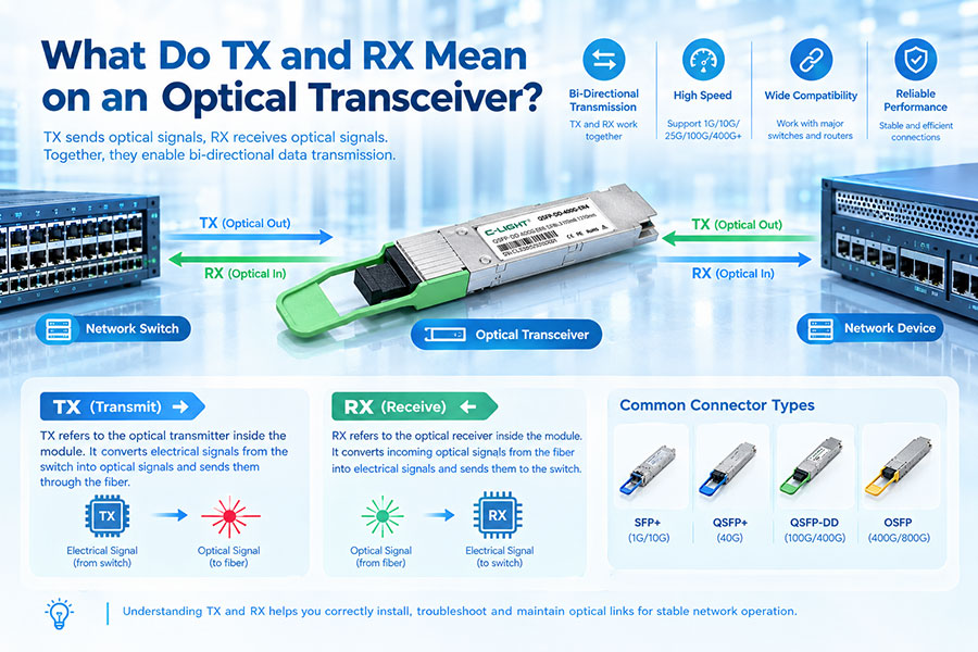
4. TX Optical Power: Monitoring the Transmitter Output
TX optical power indicates the output power generated by the transceiver's optical transmitter. It is commonly reported in dBm or milliwatts (mW).
This reading helps engineers determine whether the local module is producing optical output within its specified operating range.
Abnormal TX power readings may be associated with:
Laser output degradation.
Transmitter operating conditions outside the specified range.
Temperature or supply voltage problems.
Internal laser or transmitter circuit faults.
Module aging or component instability.
For example, if a module previously reported stable TX power but its reading gradually decreases, the change may indicate a transmitter-related issue. Engineers should compare the reading with the module's datasheet limits and confirm the condition using suitable external test equipment when necessary.
A stable TX power reading does not prove that the complete outgoing optical path is loss-free. DOM/DDM monitors the transmitter inside the module, not every connector and fiber section after it.
5. RX Optical Power: Monitoring the Incoming Signal
RX optical power measures the optical signal entering the receiver. It is one of the most useful DOM/DDM values for troubleshooting fiber links because it provides an indication of the power level arriving from the remote transmitter.
A low RX power reading may be associated with:
Excessive fiber attenuation.
Dirty, damaged or poorly connected optical interfaces.
Incorrect fiber routing or unsuitable optical components.
Excessive splitter, splice or WDM component loss.
Low transmit power at the remote endpoint.
Fiber bending or physical damage.
A high RX power reading can also be important. If the received signal exceeds the receiver's overload limit, the transceiver may not operate correctly. This can occur on a short, low-loss connection or a link with an optical amplifier.
RX power should always be compared with the specific module's receiver sensitivity and overload specifications. A reading that is acceptable for one optical module may be outside the permitted range for another.
6. TX Bias Current: Monitoring Laser Operating Behavior
TX bias current is the electrical current used to drive the optical transmitter's laser. It is commonly measured in milliamps (mA).
Laser bias current is useful because changes in the required drive current can indicate changes in transmitter operating behavior. For example, a laser may require a higher bias current over time to maintain a similar optical output level.
Engineers commonly examine TX bias current together with TX optical power and module temperature.
| Observed Pattern | Possible Interpretation | Recommended Check |
|---|---|---|
| Bias current rises while TX power remains stable | Possible change in laser efficiency or operating condition | Review the trend and compare with module specifications |
| Bias current and TX power both fall | Possible transmitter or internal circuit problem | Check module alarms and verify optical output externally |
| Bias current changes with temperature | Possible temperature-related transmitter behavior | Check thermal conditions and operating limits |
| Bias current reaches a warning or alarm threshold | Transmitter operating condition is outside the configured threshold | Review the module datasheet and consider further testing |
Bias current alone cannot confirm laser failure. It should be interpreted alongside output power, temperature, alarm status and the module's historical readings.
7. Module Temperature and Supply Voltage Monitoring
DOM/DDM also monitors the operating environment inside the optical transceiver. Temperature and supply voltage can affect laser performance, receiver operation and overall module reliability.
Temperature: The sensor reports the module's internal temperature. A high reading may indicate poor equipment ventilation, excessive ambient temperature, cooling-system problems or operation outside the specified environmental range.
Supply voltage: The voltage reading indicates the electrical supply level available to the module. Values outside the specified range may point to a host power issue, module electrical fault or unstable operating condition.
Both parameters should be checked against the exact module datasheet. Different optical transceivers can have different operating temperature ranges, power consumption and voltage limits.
8. What Are High and Low Alarm and Warning Thresholds?
Many DOM/DDM-enabled modules contain predefined diagnostic thresholds. The host device or management software can compare the measured values with these thresholds and report abnormal conditions.
Four common threshold levels are used:
| Threshold | Meaning | Typical Significance |
|---|---|---|
| High Alarm | Measured value exceeds the high alarm limit | Critical high-side condition requiring attention |
| High Warning | Measured value exceeds the high warning limit | Abnormal high-side condition approaching the alarm range |
| Low Warning | Measured value falls below the low warning limit | Abnormal low-side condition approaching the alarm range |
| Low Alarm | Measured value falls below the low alarm limit | Critical low-side condition requiring attention |
For example, an RX power low warning may indicate that the received signal is approaching the lower operating limit. A low alarm indicates that the reading has crossed the configured alarm threshold.
Threshold values are module-specific. A long-reach transceiver and a short-reach transceiver can have different output power, receiver sensitivity and overload characteristics. Operators should not apply one universal set of alarm limits to every optical module.
9. How Does DOM/DDM Work Inside an Optical Transceiver?
DOM/DDM relies on internal monitoring circuitry, sensors and a digital management interface. The module measures selected electrical and optical parameters and makes the corresponding values available to the host device.
The process generally follows these stages:
↓
Analog Measurement and Conversion
↓
Digital Values and Diagnostic Thresholds
↓
Module Management Registers
↓
Host Device Reads Diagnostic Information
For SFP-family modules, the management interface commonly follows the two-wire serial interface described by SFF-8472. The host can read the module identification information and diagnostic data through the management interface.
For four-lane and higher-density transceivers, other management specifications may apply. SFF-8636 is used by many QSFP-family modules, while CMIS is used across several modern pluggable form factors, including QSFP-DD and OSFP implementations.
The host system periodically retrieves the available values. The refresh interval depends on the equipment software and monitoring implementation, so DOM/DDM is better understood as periodic or pseudo-real-time monitoring rather than continuous laboratory measurement.
10. DOM/DDM in SFP, SFP+, QSFP28 and Modern High-Speed Modules
DOM/DDM is not limited to one optical transceiver form factor. Different module families use different management interfaces and can expose different levels of diagnostic detail.
| Module Type | Common Management Specification | Typical Diagnostic Capability |
|---|---|---|
| SFP / SFP+ | SFF-8472 | Temperature, voltage, TX bias, TX power and RX power |
| SFP28 | SFF-8472-based management in applicable implementations | Core diagnostics, with support depending on module implementation |
| QSFP+ / QSFP28 | SFF-8636 | Module-level and supported lane-level diagnostics |
| QSFP-DD | CMIS-based management in applicable implementations | Module and multiple optical-lane monitoring |
| OSFP | CMIS-based management in applicable implementations | Module and lane-level diagnostics, depending on design |
High-speed transceivers can contain multiple optical lanes. Their management interfaces may report separate TX power, RX power and bias current readings for each lane, allowing engineers to identify an issue affecting only one optical channel.
Not every module exposes every possible diagnostic field. Monitoring support and available data must be verified against the exact module specification and management standard.
11. How to Read DOM/DDM Information on a Switch or Router
When a compatible transceiver is installed, the host device can retrieve its diagnostic information through the module management interface. Network operating systems generally display the values through command-line tools, web interfaces or network management platforms.
Common information displayed includes:
Transceiver manufacturer and part number.
Module serial number and wavelength information.
Temperature and supply voltage.
TX and RX optical power.
Laser bias current.
High and low warning or alarm status.
The exact command varies by switch or router platform. Some systems provide a command such as show interfaces transceiver or show interfaces diagnostics optics, while other platforms use different syntax and menu structures.
12. How to Use TX and RX Power Readings for Fault Diagnosis
Comparing the local and remote transceiver readings can help identify which part of a fiber link may be responsible for an abnormal optical power level.
For example, if the local transmitter reports normal TX power but the remote receiver reports significantly lower RX power than expected, the optical path between the two modules should be investigated.
| DOM/DDM Observation | Possible Cause | Next Diagnostic Step |
|---|---|---|
| Local TX power is below specification | Transmitter or module operating problem | Check TX bias, temperature, voltage and module status |
| Remote RX power is lower than expected | Fiber loss, connector contamination or damaged optical path | Inspect connectors and measure the optical path |
| RX power is below the low alarm threshold | Insufficient received optical power | Check remote TX power, fiber loss and receiver sensitivity |
| RX power exceeds the high alarm threshold | Receiver overload or excessive incoming optical power | Compare with receiver overload specification and system design |
| Temperature is above the high warning threshold | High module or equipment temperature | Check airflow, ambient temperature and equipment cooling |
| Voltage is outside the specified range | Host power or module electrical problem | Check host port condition and module compatibility |
| One lane has abnormal RX power | Lane-specific optical path or module issue | Compare individual lane readings and inspect the corresponding fiber path |
These observations are diagnostic clues, not automatic fault confirmations. A low RX reading, for example, could result from a remote transmitter problem, fiber loss, a connector issue or a measurement discrepancy. Further inspection is needed to determine the actual cause.
13. How Accurate Is DOM/DDM Data?
DOM/DDM readings are intended for equipment monitoring and diagnostics. They should not automatically be treated as equivalent to measurements from calibrated optical test instruments.
Accuracy depends on the management specification, sensor design, calibration method, temperature range and module implementation. For example, SFF-8472 defines measurement accuracy requirements for applicable SFP diagnostic interfaces, including tolerances for optical power, temperature, supply voltage and bias current.
Two important calibration methods are used:
Internal calibration: The module converts its sensor readings into engineering units before reporting the values to the host.
External calibration: The host uses calibration constants supplied by the module to convert raw measurement data into engineering units.
The host must interpret the module's calibration information correctly. Incorrect scaling or calibration handling can lead to misleading displayed readings.
When a precise optical power measurement is required, an appropriate calibrated optical power meter should be used. DOM/DDM is valuable for monitoring trends and identifying abnormal conditions, while external instruments are used for more controlled measurements and verification.
14. What DOM/DDM Cannot Measure
DOM/DDM is useful, but its scope is limited to the diagnostic functions implemented by the transceiver. Normal power readings do not prove that every aspect of the optical signal is healthy.
Traditional DOM/DDM does not necessarily provide direct measurements of:
Bit Error Rate: The actual rate of bit errors in the received data stream.
Eye diagram quality: Signal opening, jitter and waveform distortion.
Chromatic dispersion: Pulse spreading caused by wavelength-dependent propagation delay.
Optical signal-to-noise ratio: The relationship between signal power and optical noise in the link.
Fiber location of a fault: The physical distance to a damaged section of fiber.
All lane-level signal impairments: The available monitoring depends on the module's management interface.
A link can therefore show normal TX and RX power while still experiencing high BER, excessive jitter, dispersion or signal-integrity problems. These conditions require additional diagnostics such as BER testing, FEC counter analysis, eye diagram measurements or optical spectrum analysis.
15. DOM/DDM vs Optical Power Meter and Other Test Instruments
DOM/DDM and external optical test instruments serve complementary roles. DOM/DDM provides in-service information from the installed transceiver, while external instruments provide measurements of the fiber link or optical signal under defined test conditions.
| Tool | Primary Measurement | Typical Use |
|---|---|---|
| DOM/DDM | Module temperature, voltage, bias current and optical power | Routine monitoring and preliminary fault diagnosis |
| Optical Power Meter | Optical power at a selected wavelength | Verifying transmitter output or received optical power |
| Optical Loss Test Set | Insertion loss across a fiber link | Fiber installation and link qualification |
| OTDR | Fiber reflections, loss events and approximate event locations | Fiber fault location and plant characterization |
| Bit Error Rate Tester | Bit error performance | Transceiver and link performance validation |
| Optical Spectrum Analyzer | Optical power distribution across wavelengths | CWDM, DWDM and multi-wavelength system testing |
For operational networks, DOM/DDM is often the first diagnostic reference. When readings indicate an abnormal condition, external test instruments can help confirm the fault and locate its source.
16. What Should Be Checked When DOM/DDM Is Not Available?
Some optical transceivers do not implement digital diagnostics, and some host platforms do not support every diagnostic function. A missing DOM/DDM display does not automatically mean the optical module is defective.
When diagnostic data is unavailable, check the following:
Confirm whether the specific module model supports DOM/DDM.
Check whether the module's management interface is supported by the host device.
Verify the switch or router firmware and diagnostic command support.
Confirm that the module is correctly recognized by the platform.
Check whether the relevant diagnostic fields are optional or unsupported for that module type.
Use an external optical power meter when TX or RX power needs to be verified.
For QSFP-DD and OSFP modules, the host platform may use CMIS rather than the traditional SFP DDM interface. Engineers should therefore check the relevant management specification for the actual form factor.
17. C-LIGHT Optical Transceivers with DDM/DOM Support
C-LIGHT offers optical transceiver products with digital diagnostic monitoring capabilities. The exact diagnostic support should be confirmed using the individual model datasheet, particularly when a project requires specific TX/RX monitoring, temperature thresholds or multi-lane diagnostics.
100G QSFP28 ER4 Optical Transceiver
The C-LIGHT CL100GQSFPER4 is a 100G single-mode optical transceiver designed for transmission distances up to 40 km. It uses four LAN-WDM optical lanes around the 1310 nm region, a duplex LC interface and built-in digital diagnostic monitoring.
The product specification lists DDM/DOM support, allowing the host system to access supported diagnostic information for module monitoring and link maintenance.
25G CWDM 20 km Optical Module
C-LIGHT 25G CWDM modules include digital diagnostic monitoring through the I²C management interface. Supported readings include optical output power, received power, module temperature, voltage and laser bias current.
This capability helps network operators monitor optical operating conditions on CWDM access and transport links.
When requesting optical transceivers with DOM/DDM, specify the data rate, form factor, wavelength, transmission distance, host platform and required monitoring parameters. This helps confirm that the selected module and host system provide the expected diagnostic functionality.
18. Conclusion
DOM and DDM are commonly used names for digital diagnostic monitoring functions in optical transceivers. They allow compatible network equipment to retrieve important operating information, including temperature, supply voltage, laser bias current, transmit power and receive power.
These readings help engineers monitor module health, identify abnormal optical power conditions and investigate changes in fiber link performance. Alarm and warning thresholds provide additional indications when monitored values move outside their configured operating ranges.
However, DOM/DDM is a monitoring tool rather than a complete optical test system. It does not independently measure BER, eye diagram quality, dispersion or every possible fiber fault. Reliable troubleshooting combines module diagnostics with the appropriate optical measurement and network testing tools.
Looking for optical transceivers with DOM/DDM support?
Contact C-LIGHT for optical module specifications, diagnostic monitoring options and compatibility support for data center, enterprise and telecom networks.
 >

 >
 >
 >
 >
 >
 >
 >