TEL:+86 132 6656 7067




1. Introduction
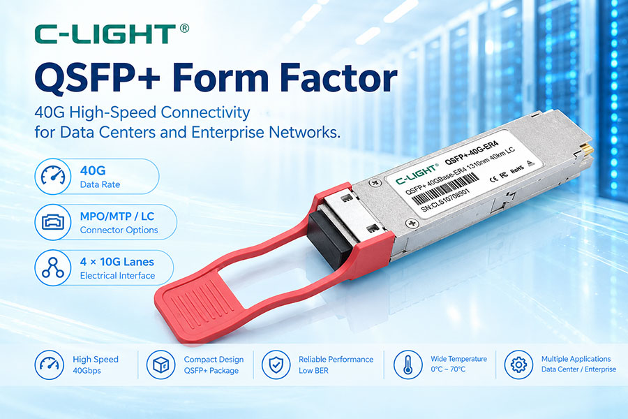
QSFP+ stands for Quad Small Form-factor Pluggable Plus. It is a compact, hot-pluggable transceiver form factor developed mainly for 40Gbps-class networking. Its four-lane architecture provides higher aggregate bandwidth than single-lane SFP-family modules while maintaining relatively high port density.
2. What Is the QSFP+ Form Factor?
QSFP+ defines the mechanical and electrical interface between a four-lane pluggable module and the host system. The architecture is commonly associated with 40GbE, Fibre Channel, InfiniBand, and other high-speed networking applications.
3. Why Was QSFP+ Developed?
As network bandwidth increased, single-lane 10G modules became inefficient for higher aggregate throughput. QSFP+ combines four lower-speed lanes within one module, allowing a 40G connection without using four separate SFP+ ports.
4. QSFP+ Four-Lane Architecture
The basic QSFP+ architecture uses four transmit lanes and four receive lanes. In common 40G implementations, each lane operates at approximately 10Gbps, providing an aggregate data rate of about 40Gbps.
5. QSFP+ Mechanical Design
QSFP+ uses a compact rectangular housing with a host-side electrical interface and a front optical or copper interface. A bail-style latch is commonly used to secure and remove the module from the host cage.
6. QSFP+ Module Size
The QSFP+ package is wider than SFP and SFP+ but supports four high-speed channels in a single module position. The SFF-8436 mechanical specification defines the module envelope and cage interface, including an approximately 18.35mm module width and 8.5mm height at the front section.
7. QSFP+ Cage
The QSFP+ cage is mounted on the host PCB and provides mechanical alignment, grounding, shielding, retention, and thermal contact. The cage can accommodate optical transceivers as well as compatible direct-attach cable assemblies.
8. QSFP+ Electrical Connector
QSFP+ uses a 38-contact electrical interface. The contacts provide four high-speed transmit pairs, four high-speed receive pairs, power, ground, management, and control signals.
9. QSFP+ Power Supply
QSFP+ uses a 3.3V-class power architecture. Separate supply connections can serve transmitter and receiver functions, while the actual module power depends on the optical design, electronics, reach, and thermal requirements.
10. Hot-Pluggable Operation
QSFP+ is designed for hot-plug operation on compatible host equipment. Modules can be installed or removed without powering down the entire networking system when the host platform supports this function.
11. QSFP+ Electrical Signal Path
The host ASIC or SerDes sends four electrical transmit lanes into the QSFP+ module. The transceiver converts these signals into optical or electrical output, while four receive lanes return data from the remote connection to the host.
12. Optical QSFP+ Modules
Optical QSFP+ modules convert electrical data into optical signals and back again. They are available for multimode and single-mode fiber, with different laser technologies, wavelengths, connectors, and transmission distances.
13. QSFP+ Multimode Applications
Short-reach QSFP+ modules commonly use 850nm VCSEL technology with multimode fiber. 40GBASE-SR4 is a typical example, using parallel optical lanes for short data center connections.
14. QSFP+ Single-Mode Applications
Single-mode QSFP+ modules are used for longer-distance transmission. Designs such as LR4 and ER4 use multiple optical wavelengths or channels to achieve longer reach over single-mode fiber.
15. QSFP+ Optical Connectors
MPO or MTP interfaces are commonly associated with parallel-fiber QSFP+ modules such as SR4. Duplex LC can also be used in wavelength-multiplexed designs such as LR4 and ER4.
16. QSFP+ Wavelengths
QSFP+ modules can operate at different wavelengths depending on the optical architecture. Short-reach multimode solutions commonly use 850nm, while single-mode designs can use 1310nm-class CWDM wavelengths or other wavelength arrangements.
17. QSFP+ Transmitter
The transmitter section contains optical sources and driving circuitry for the four transmit channels. VCSEL arrays are commonly used for short-reach modules, while DFB or other laser technologies can be used for longer-reach designs.
18. QSFP+ Receiver
The receiver uses photodetectors and receiver circuitry to convert incoming optical signals into electrical signals. Receiver sensitivity and overload performance contribute directly to the achievable link budget.
19. QSFP+ Management Interface
QSFP+ includes a low-speed management interface based on a two-wire serial bus. The host can use it to identify the module, access operating information, and perform supported management functions.
20. Digital Diagnostic Monitoring
Many QSFP+ modules support digital diagnostics. Depending on the implementation, parameters such as temperature, voltage, transmit power, receive power, and laser bias can be monitored.
21. QSFP+ Module Coding
Module memory can contain vendor information, part number, serial number, wavelength, supported characteristics, and monitoring data. In some networking systems, coding compatibility is important for module recognition and acceptance.
22. QSFP+ Signal Integrity
Four high-speed electrical lanes make signal integrity especially important. PCB insertion loss, connector quality, impedance control, crosstalk, via transitions, and host SerDes characteristics can affect link performance.
23. QSFP+ and NRZ Signaling
Traditional 40G QSFP+ implementations commonly use NRZ signaling, with approximately 10Gbps per lane. This differs from newer QSFP28, QSFP56, QSFP-DD, and OSFP generations that increasingly use higher lane rates and PAM4.
24. QSFP+ Breakout Applications
A major advantage of the four-lane architecture is breakout connectivity. A 40G QSFP+ interface can be used in suitable systems as a 4×10G connection, allowing one high-density port to connect to four lower-speed ports.
25. QSFP+ DAC and AOC
The QSFP+ form factor is not limited to optical transceivers. Direct Attach Copper (DAC) and Active Optical Cable (AOC) assemblies can also use QSFP+ connectors for short-reach switch-to-switch and other high-bandwidth connections.
26. QSFP+ Power and Thermal Design
Because one QSFP+ module contains multiple transmit and receive channels, its thermal behavior must be considered at the module and system levels. Cage spacing, heat sinks, airflow, and host chassis design affect reliable operation.
27. QSFP+ Link Budget
For optical QSFP+, the link budget combines transmitter output power, fiber attenuation, connector loss, passive component loss, and receiver sensitivity. Sufficient optical margin is required for stable transmission.
28. QSFP+ Transmission Reach
Reach depends on the specific optical standard. For example, 40GBASE-SR4 is designed for short multimode links, while LR4 and ER4 extend transmission over single-mode fiber to longer distances. The exact reach depends on the module specification and fiber installation.
29. QSFP+ vs SFP+
| Feature | SFP+ | QSFP+ |
|---|---|---|
| Typical Aggregate Rate | 10Gbps | 40Gbps |
| Lane Architecture | 1 lane | 4 lanes |
| Physical Size | Smaller | Larger |
| Typical Connector | LC / RJ45 | MPO / LC / Other |
| Typical Applications | 10GbE | 40GbE, storage, InfiniBand |
30. QSFP+ vs QSFP28
| Feature | QSFP+ | QSFP28 |
|---|---|---|
| Typical Aggregate Rate | 40Gbps | 100Gbps |
| Typical Lane Rate | 10Gbps-class | 25Gbps-class |
| Common Signaling | NRZ | NRZ |
| Physical Interface | QSFP family | QSFP family |
| Typical Application | 40GbE | 100GbE |
31. QSFP+ vs QSFP-DD
QSFP-DD extends the QSFP concept with a double-density electrical interface and additional lanes. It is designed for much higher aggregate speeds such as 200G, 400G, and 800G, while QSFP+ is primarily associated with 40G-class applications.
32. QSFP+ vs OSFP
QSFP+ and OSFP use different mechanical architectures. OSFP is physically larger and was developed for newer high-speed applications such as 800G and beyond, while QSFP+ remains a widely recognized 40G form factor.
33. QSFP+ Compatibility
Compatibility requires more than matching the cage. The host must support the module's data rate, lane configuration, electrical interface, optical specification, management interface, coding, and intended protocol.
34. QSFP+ in Data Center Networks
QSFP+ has been widely used in 40G data center switching, server aggregation, leaf-spine networks, and short-reach interconnects. Its four-lane architecture provides efficient high-density connectivity compared with multiple independent 10G ports.
35. QSFP+ in Telecom and Storage
QSFP+ can also be used in telecom, Fibre Channel, InfiniBand, and specialized networking systems. The appropriate module depends on the required protocol, optical reach, wavelength, and host interface.
36. Advantages of the QSFP+ Form Factor
QSFP+ provides four-channel architecture, high aggregate bandwidth, hot-pluggable operation, compact port density, optical and copper options, and flexible breakout connectivity.
37. Limitations of QSFP+
QSFP+ is primarily a 40G-generation technology. Newer networks requiring 100G, 400G, 800G, or 1.6T commonly use more advanced form factors and higher per-lane signaling technologies.
38. QSFP+ and Network Evolution
QSFP+ established the four-channel architecture that influenced later QSFP-family generations. QSFP28 increased lane speed for 100G, QSFP56 moved to 50G-class lanes, and QSFP-DD further increased lane density for higher-speed networking.
39. QSFP+ Selection Guide
When selecting a QSFP+ module, check the host port, 40G support, lane architecture, optical wavelength, fiber type, connector, reach, optical budget, power consumption, temperature range, management support, and module coding.
40. Frequently Asked Questions
Q1. What is the QSFP+ form factor?
Q2. How many lanes does QSFP+ use?
Q3. What is the typical speed of QSFP+?
Q4. What connector does QSFP+ use?
Q5. Can QSFP+ support breakout connections?
Q6. Is QSFP+ compatible with QSFP28?
Q7. Can QSFP+ be used with DAC cables?
Q8. What should be checked before selecting a QSFP+ module?
41. Summary
QSFP+ is a four-lane pluggable transceiver form factor primarily designed for 40Gbps-class networking. Its compact mechanical package, 38-contact electrical interface, hot-pluggable design, and four-channel architecture made it an important step in the development of high-density optical networking. QSFP+ supports multiple optical and cable technologies, including short-reach multimode, longer-reach single-mode, DAC, and AOC solutions. Although newer form factors now serve higher-speed networks, QSFP+ remains relevant in 40G data center, storage, InfiniBand, telecom, and legacy networking environments. Proper host, lane, optical, electrical, and coding compatibility remains essential for deployment.
 >
>

 >
>
 >
>
 >
>
 >
>
 >
>
 >
>
 >
>