TEL:+86 132 6656 7067




1. Introduction
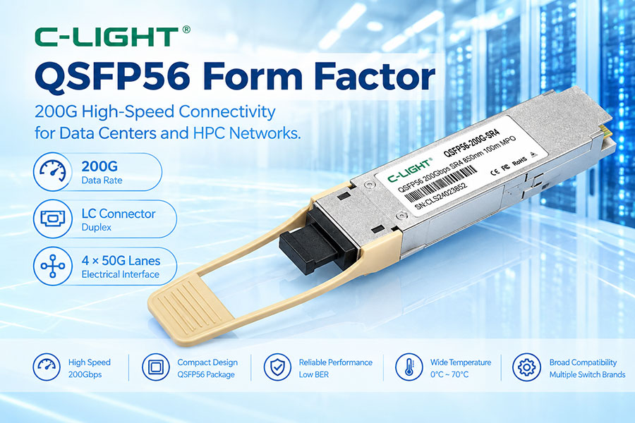
QSFP56 is a high-speed member of the QSFP family designed for four-lane pluggable connectivity. It is commonly used for 200G-class networking, with each electrical lane operating in the 50G-class range. QSFP56 maintains the compact QSFP mechanical concept while increasing lane speed significantly compared with QSFP28.
2. What Is the QSFP56 Form Factor?
QSFP56 defines a four-lane pluggable architecture covering mechanical, low-speed electrical, and management interfaces. The "56" refers to the lane-rate class rather than a fixed 56Gbps Ethernet payload. In common 200G implementations, four 50G-class lanes are used with PAM4 signaling.
3. Why Was QSFP56 Developed?
The growth of 100G networks created demand for more bandwidth per port without requiring a major increase in module size. QSFP56 increases the lane rate from the 25G-class of QSFP28 to the 50G-class, enabling 200G connectivity in a compact four-lane package.
4. QSFP56 Four-Lane Architecture
A typical QSFP56 interface has four transmit lanes and four receive lanes. For 200G Ethernet, the electrical interface is commonly based on 4 × 50G-class PAM4 lanes, while the optical implementation can use four parallel optical channels or four wavelengths depending on the module type.
5. QSFP56 and 200G Networking
QSFP56 is strongly associated with 200GbE deployments. Examples include 200GBASE-SR4 and 200GBASE-FR4, where the QSFP56 package provides a compact interface for 200G-class optical connectivity.
6. QSFP56 Mechanical Design
QSFP56 uses the familiar rectangular QSFP-style housing with an electrical connector at the rear and an optical or cable interface at the front. A pull tab or bail latch is normally used for module insertion and removal.
7. QSFP56 Dimensions
QSFP56 follows the compact QSFP mechanical envelope. Typical optical modules are approximately 18.4mm wide and 8.5mm high, while module depth varies according to the specific implementation and mechanical reference.
8. QSFP56 Cage
The QSFP56 cage is mounted on the host PCB and provides mechanical alignment, retention, grounding, shielding, and thermal contact. High-density cage placement also affects airflow and front-panel thermal performance.
9. QSFP56 Electrical Connector
QSFP56 uses the four-lane QSFP electrical interface with a 38-contact connection. The interface carries high-speed transmit and receive signals together with power, ground, management, and control functions.
10. QSFP56 Hot-Pluggable Design
QSFP56 is designed for hot-plug operation on compatible host platforms. This allows network operators to replace, upgrade, or service modules without powering down the complete networking system.
11. QSFP56 Electrical Interface
200G QSFP56 implementations commonly use 200GAUI-4, with four 50G-class electrical lanes. Compared with QSFP28, the higher lane rate places greater requirements on PCB routing, connector performance, host SerDes, equalization, and signal integrity.
12. QSFP56 and PAM4
Modern 200G QSFP56 Ethernet modules commonly use PAM4 signaling. PAM4 provides four amplitude levels and carries two bits per symbol, allowing higher data rates without simply doubling the electrical bandwidth required by an equivalent NRZ system.
13. QSFP56 Optical Architecture
QSFP56 can support several optical architectures. Parallel-fiber modules use multiple optical lanes, while wavelength-multiplexed designs combine multiple wavelengths over fewer fibers. The form factor itself does not define one specific optical technology.
14. QSFP56 SR4
200GBASE-SR4 is a short-reach QSFP56 application commonly using 850nm optical channels and multimode fiber. An MPO-12 interface is typically used for the parallel-fiber connection.
15. QSFP56 FR4
200GBASE-FR4 uses four wavelength channels over duplex single-mode fiber. The four wavelengths are multiplexed within the module, allowing a duplex LC interface while supporting a reach of up to around 2km in common implementations.
16. QSFP56 Multimode Fiber
Short-reach QSFP56 modules commonly use 850nm VCSEL-based optics with OM3, OM4, or OM5 multimode fiber. Reach depends on the module specification, fiber type, connector loss, and link conditions.
17. QSFP56 Single-Mode Fiber
Longer-reach QSFP56 designs use single-mode fiber and can employ multiple wavelengths. FR4 is a common example of a wavelength-multiplexed single-mode implementation.
18. QSFP56 Optical Connectors
MPO/MTP connectors are common for parallel-fiber QSFP56 modules such as SR4. Duplex LC is commonly used for wavelength-multiplexed designs such as FR4.
19. QSFP56 Transmitter
The transmitter contains four high-speed optical channels together with the corresponding laser and driver functions. VCSEL technology is common for short-reach multimode applications, while longer-reach modules can use other laser architectures.
20. QSFP56 Receiver
The receiver converts incoming optical signals into electrical signals using photodetectors and receiver electronics. Receiver sensitivity, overload performance, and per-lane signal quality contribute to the total link performance.
21. QSFP56 Management Interface
QSFP56 modules include a low-speed management interface for identification, monitoring, configuration, and status reporting. The host can access module information through the standard management mechanism supported by the QSFP family.
22. EEPROM and Module Identification
Module memory can contain vendor information, part number, serial number, optical characteristics, supported capabilities, and diagnostic information. Accurate module identification can also be important for host compatibility.
23. QSFP56 Digital Diagnostics
Many QSFP56 modules support digital monitoring of parameters such as temperature, supply voltage, transmit optical power, receive optical power, and laser bias. Per-channel information can help isolate faults in high-speed links.
24. QSFP56 Power Consumption
QSFP56 power consumption depends on the laser technology, driver, receiver, DSP or signal-conditioning architecture, monitoring circuitry, and operating conditions. A 200G module normally requires more power than a comparable 100G module because of its higher lane rate and processing requirements.
25. QSFP56 Thermal Management
Higher-speed electronics generate more heat, making thermal design important. Module heat sinks, cage airflow, chassis design, port spacing, and ambient temperature all affect stable QSFP56 operation.
26. QSFP56 Signal Integrity
50G-class electrical lanes have tighter channel requirements than 25G-class lanes. PCB insertion loss, crosstalk, impedance discontinuities, vias, connector characteristics, and host SerDes equalization must be controlled to maintain adequate signal quality.
27. QSFP56 and FEC
200G PAM4 links are more sensitive to noise and signal impairments than traditional NRZ links. FEC is therefore commonly used in 200G Ethernet architectures, although the exact implementation and requirements depend on the optical and host standard.
28. QSFP56 Breakout Capability
QSFP56 can support breakout connectivity in compatible platforms. A common example is a 200G QSFP56 port connecting to four 50G links, while some implementations can also support other breakout configurations depending on the host and module architecture.
29. QSFP56 DAC and AOC
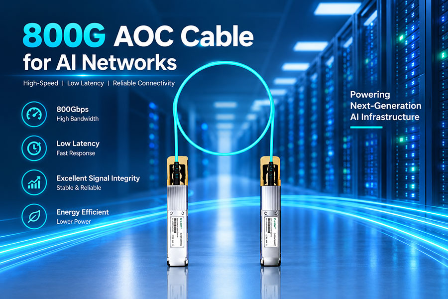
The QSFP56 form factor is also used for direct-attach copper cables and active optical cables. These solutions provide short-reach 200G connectivity without requiring separate optical transceivers at both ends.
30. QSFP56 and QSFP28
| Feature | QSFP28 | QSFP56 |
|---|---|---|
| Common Aggregate Rate | 100G | 200G |
| Typical Lane Rate | 25G-class | 50G-class |
| Typical Signaling | NRZ | PAM4 |
| Lane Count | 4 | 4 |
| Typical Application | 100GbE | 200GbE |
31. QSFP56 and QSFP+
QSFP+ is primarily associated with 40G networking using four 10G-class lanes. QSFP56 increases the lane rate substantially and is commonly used for 200G-class networking, while keeping the four-lane QSFP concept.
32. QSFP56 and SFP56
QSFP56 and SFP56 both use 50G-class lane technology, but they are different form factors. QSFP56 uses four lanes in one module, while SFP56 is a single-lane 50G-class solution.
33. QSFP56 and QSFP-DD
QSFP-DD adds a second row of electrical contacts and provides greater lane density than QSFP56. QSFP-DD is therefore used for higher aggregate rates such as 400G and 800G, while QSFP56 is commonly used for 200G.
34. QSFP56 and OSFP
OSFP uses a larger mechanical architecture and was designed for newer high-speed generations. QSFP56 retains the smaller QSFP-family package and is widely associated with 200G-class networking.
35. QSFP56 Compatibility
Compatibility requires more than matching the physical cage. The host must support the required lane rate, electrical interface, module management, coding, power class, and operating mode. The optical variant must also match the fiber and remote-end requirements.
36. QSFP56 Module Coding
Some host platforms use module identification and coding information to determine whether a transceiver is supported. Correct EEPROM data can therefore be important for third-party, replacement, and multi-vendor QSFP56 deployment.
37. QSFP56 in AI and Data Center Networks
QSFP56 is useful in data center architectures requiring 200G connectivity between switches, servers, NICs, and other network devices. Its four-lane architecture also provides a practical transition between 100G QSFP28 and higher-speed QSFP-DD or OSFP platforms.
38. QSFP56 Applications
Typical applications include 200GbE data center links, switch-to-switch connections, server and NIC connectivity, high-speed aggregation, breakout architectures, DAC, AOC, and selected telecom or interconnect systems.
39. Advantages of the QSFP56 Form Factor
Key advantages include 200G-class bandwidth, four-lane architecture, compact QSFP-family packaging, hot-plug capability, optical and cable options, and flexible breakout support.
40. Limitations of the QSFP56 Form Factor
QSFP56 requires higher-performance electrical channels and signal processing than earlier QSFP generations. PAM4 also introduces tighter signal-quality requirements, and the form factor does not provide the lane density of newer QSFP-DD and OSFP solutions.
41. QSFP56 Selection Guide
When selecting a QSFP56 module, check the host interface, supported 200G standard, lane architecture, optical technology, wavelength, fiber type, connector, reach, FEC requirements, module coding, power consumption, temperature range, and diagnostic support.
42. Frequently Asked Questions
Q1. What is the QSFP56 form factor?
Q2. Does QSFP56 always mean exactly 56Gbps per lane?
Q3. What is the typical application of QSFP56?
Q4. How many lanes does QSFP56 use?
Q5. Does QSFP56 use PAM4?
Q6. What connectors are used with QSFP56?
Q7. Can QSFP56 support breakout?
Q8. What should be checked before installing QSFP56?
43. Summary
QSFP56 extends the QSFP architecture into the 50G-class lane generation and is commonly used for 200G networking. Its four-lane design, compact package, PAM4 signaling, and support for optical transceivers, DAC, and AOC make it suitable for high-density data center connectivity. Common implementations include parallel-fiber 200GBASE-SR4 and wavelength-multiplexed 200GBASE-FR4. Compared with QSFP28, QSFP56 doubles the typical lane rate and aggregate bandwidth while introducing tighter signal-integrity, thermal, and FEC requirements. Proper host compatibility, optical selection, module coding, and link-budget verification remain essential for reliable deployment.
 >
>

 >
>
 >
>
 >
>
 >
>
 >
>
 >
>
 >
>