TEL:+86 132 6656 7067




1. Introduction
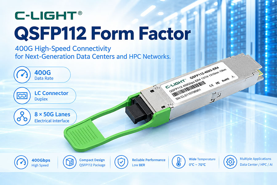
QSFP112 is a high-speed four-lane pluggable form factor designed for 112G-class electrical signaling per lane. It brings 400G-class connectivity into the compact QSFP family and is increasingly used in high-speed data center, Ethernet, and AI networking.
2. What Is the QSFP112 Form Factor?
QSFP112 defines the mechanical, electrical, thermal, and management characteristics of a four-channel pluggable module. The “112” refers to the 112Gbps signaling class of each host electrical lane rather than a 112Gbps aggregate module rate.
3. Why Was QSFP112 Developed?
As 400G networking moved toward higher per-lane speeds, the industry needed a compact alternative to architectures requiring more electrical lanes. QSFP112 uses four 112G-class lanes to support a 400G-class connection while retaining the familiar QSFP-style package.
4. QSFP112 Four-Lane Architecture
A typical QSFP112 interface provides four transmit and four receive electrical lanes. Each lane operates in the 112G signaling class, commonly using PAM4, enabling a four-lane architecture for 400G networking.
5. QSFP112 and 400G Networking
QSFP112 is primarily associated with 400G-class connectivity. It can be used with optical transceivers, DACs, AOCs, and different optical architectures depending on the host platform and application.
6. QSFP112 Mechanical Design
QSFP112 retains the compact rectangular structure of the QSFP family. The module includes a host-side electrical interface, an optical or cable interface, and a pull mechanism for installation and removal.
7. QSFP112 Dimensions
The QSFP112 mechanical package remains closely related to the established QSFP family. Its compact dimensions support high port density, while the detailed mechanical envelope, flatness, and thermal surfaces are defined by the QSFP112 MSA.
8. QSFP112 Cage
The host cage provides mechanical alignment, retention, grounding, shielding, and thermal contact. QSFP112 cage design is particularly important for high-speed signal integrity and thermal management.
9. QSFP112 Electrical Connector
QSFP112 uses a four-lane QSFP electrical interface with a 38-contact connector arrangement. The contacts provide high-speed data, power, ground, management, and control functions.
10. QSFP112 High-Speed Paddle Card
To support 112G-class signaling, the module electrical interface uses improved paddle-card pad dimensions compared with earlier QSFP generations. This helps meet the electrical requirements of higher-speed host channels.
11. QSFP112 Electrical Interface
400G QSFP112 systems commonly use four 100G-class PAM4 electrical lanes. The host electrical channel requires low loss, controlled impedance, low crosstalk, and suitable equalization to maintain signal quality at these speeds.
12. QSFP112 and PAM4
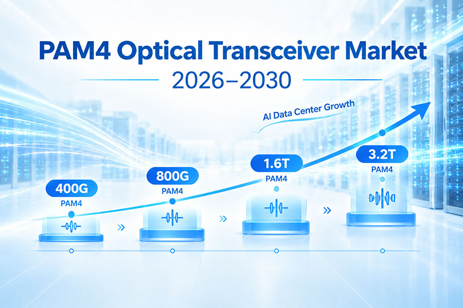
PAM4 uses four amplitude levels to transmit two bits per symbol. It allows higher lane rates without simply doubling the symbol rate, but the smaller eye openings increase sensitivity to noise, insertion loss, reflections, and other signal impairments.
13. QSFP112 Optical Architecture
QSFP112 is a form factor rather than a specific optical standard. Optical implementations can use parallel fibers or wavelength multiplexing, depending on the required distance, fiber infrastructure, and module design.
14. QSFP112 DR4
400G DR4 is a common QSFP112 optical architecture for single-mode fiber. It typically uses four parallel optical channels and an MPO interface, making it suitable for medium-reach data center interconnects.
15. QSFP112 SR4
QSFP112 can also be used with short-reach parallel multimode architectures. Depending on the implementation, 400G SR4 solutions can use multiple 850nm-class optical channels over multimode fiber.
16. QSFP112 FR4
FR4 uses four wavelength channels multiplexed onto duplex single-mode fiber. A QSFP112 FR4 module therefore combines the four-lane host architecture with wavelength-multiplexed optical transmission and an LC interface.
17. QSFP112 LR4
LR4 extends the QSFP112 architecture to longer single-mode fiber applications. Multiple wavelengths are combined within the module to provide high aggregate bandwidth over a duplex fiber connection.
18. QSFP112 Multimode Fiber
Short-reach QSFP112 implementations can use multimode fiber where supported by the optical standard. The actual reach depends on the transceiver, wavelength, fiber grade, connector loss, and installation conditions.
19. QSFP112 Single-Mode Fiber
Single-mode fiber is widely used with QSFP112 architectures designed for longer transmission distances. DR4, FR4, and LR4 illustrate different ways of delivering 400G over single-mode infrastructure.
20. QSFP112 Optical Connectors
MPO/MTP is commonly used for parallel-fiber architectures such as DR4. Duplex LC is commonly used for wavelength-multiplexed architectures such as FR4 and LR4.
21. QSFP112 Transmitter
The transmitter section contains high-speed optical sources, drivers, and related control circuitry. The optical technology depends on the specific module, with VCSEL-based and single-mode laser architectures serving different reach requirements.
22. QSFP112 Receiver
The receiver converts incoming optical signals into electrical signals through photodetectors and receiver electronics. Receiver sensitivity, overload performance, and lane-to-lane consistency are important to overall link performance.
23. QSFP112 Management
QSFP112 supports modern module management and monitoring functions. The host can obtain module identification, configuration, status, and diagnostic information according to the supported management implementation.
24. CMIS and QSFP112
High-speed QSFP112 modules can use CMIS-based management for module state control, application configuration, monitoring, and diagnostics. The exact management features depend on the module implementation and host platform.
25. Module Identification and Coding
Module memory can contain vendor information, part number, serial number, optical characteristics, compliance information, and supported applications. Correct identification and coding can be important when deploying modules in multi-vendor systems.
26. QSFP112 Digital Diagnostics
Diagnostic functions can monitor parameters such as temperature, supply voltage, transmit optical power, receive optical power, and other lane-level operating conditions. These measurements are useful for link validation and troubleshooting.
27. QSFP112 Power Consumption
Power consumption depends on the optical architecture, DSP or signal-conditioning design, laser technology, driver, receiver, and operating conditions. Higher-speed 112G-class electrical interfaces also increase pressure on overall power efficiency.
28. QSFP112 Thermal Management
High-speed QSFP112 modules require careful thermal design. Heat-sink performance, thermal contact, airflow, module spacing, and host chassis conditions all affect operating temperature and long-term stability.
29. QSFP112 Signal Integrity
112G-class electrical signaling places strict requirements on the host channel. PCB insertion loss, connector loss, crosstalk, impedance discontinuities, vias, package design, and SerDes equalization all influence signal quality.
30. QSFP112 and FEC
High-speed PAM4 links typically rely on forward error correction to achieve the required system error performance. The exact FEC implementation depends on the host standard, optical interface, and network architecture.
31. QSFP112 Breakout
Suitable QSFP112 ports can support breakout architectures in compatible systems. A 400G port can be divided into lower-speed connections according to the capabilities of the host ASIC, module, cable, and network configuration.
32. QSFP112 DAC and AOC
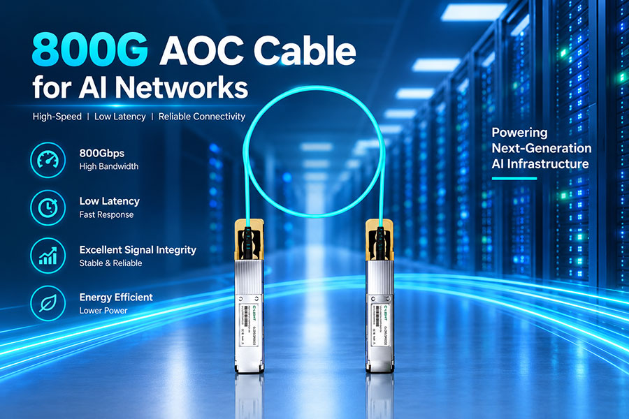
QSFP112 is not limited to optical transceivers. Compatible DAC and AOC products can provide short-reach 400G connections for switch-to-switch, server, and other high-bandwidth applications.
33. QSFP112 vs QSFP56
| Feature | QSFP56 | QSFP112 |
|---|---|---|
| Typical Aggregate Rate | 200G | 400G |
| Typical Lane Signaling | 50G-class PAM4 | 112G-class PAM4 |
| Lane Count | 4 | 4 |
| Typical Application | 200GbE | 400GbE |
34. QSFP112 vs QSFP-DD
QSFP112 and QSFP-DD can both support 400G, but they use different host-side lane architectures. QSFP112 uses four higher-speed electrical lanes, while QSFP-DD can use more lanes at lower per-lane signaling rates depending on the implementation.
35. QSFP112 vs OSFP
QSFP112 and OSFP have different mechanical designs. QSFP112 remains within the compact QSFP family, while OSFP uses a larger form factor designed for high-speed generations such as 800G and beyond.
36. QSFP112 Compatibility
Physical insertion does not guarantee compatibility. The host must support the required electrical signaling, management, power class, coding, and operating mode, while the optical interface must match the fiber, connector, wavelength, and remote-end requirements.
37. QSFP112 in Data Center Networks
QSFP112 is suited to high-density 400G switch ports, leaf-spine networks, server and NIC connections, and AI data center interconnects. Its four-lane architecture can provide high aggregate bandwidth without using the larger OSFP package.
38. QSFP112 and AI Networking
AI and HPC networks require high-bandwidth connections between accelerators, NICs, switches, and storage systems. QSFP112 can support these environments through compact 400G optical and cable solutions with high port density.
39. Advantages of the QSFP112 Form Factor
Key advantages include four-lane 400G-class connectivity, compact QSFP-family packaging, high port density, hot-plug capability, multiple optical architectures, and support for both optical and cable-based interconnects.
40. Limitations of QSFP112
The main challenge is the demanding 112G-class electrical channel. Host SerDes, PCB design, connectors, module packaging, thermal performance, and interoperability must all meet tighter requirements than earlier QSFP generations.
41. QSFP112 Selection Guide
When selecting a QSFP112 module, check the host port, electrical lane rate, optical standard, wavelength, fiber type, connector, transmission distance, FEC, management interface, module coding, power consumption, thermal conditions, and interoperability.
42. Frequently Asked Questions
Q1. What is the QSFP112 form factor?
Q2. Does QSFP112 mean 112Gbps total bandwidth?
Q3. Does QSFP112 use PAM4?
Q4. What optical types are available for QSFP112?
Q5. What connectors are commonly used?
Q6. Is QSFP112 compatible with QSFP28 or QSFP56?
Q7. Can QSFP112 support 400G breakout?
Q8. What should be checked before installing QSFP112?
43. Summary
QSFP112 brings 400G-class connectivity into a compact four-lane QSFP-family form factor by moving the host electrical interface to the 112G signaling class. Common implementations use PAM4 and four 100G-class lanes, while optical architectures can include DR4, SR4, FR4, and LR4. Compared with earlier QSFP generations, QSFP112 places greater demands on SerDes performance, signal integrity, thermal management, packaging, and interoperability. Its combination of high bandwidth, compact size, and multiple optical options makes it an important form factor for modern 400G data center, AI, HPC, and high-density networking applications.
 >
>

 >
>
 >
>
 >
>
 >
>
 >
>
 >
>
 >
>