TEL:+86 132 6656 7067





Optical transceivers and media converters are both used in fiber-optic communication networks, but they serve different purposes. An optical transceiver is a component that converts electrical signals into optical signals and converts received optical signals back into electrical signals. A media converter is a standalone networking device that connects different transmission media, commonly copper Ethernet and optical fiber.
An optical transceiver is normally installed inside a switch, router, server network adapter or compatible media converter. A media converter includes its own electronic circuitry, network interfaces and power supply. Some models use fixed optical ports, while others provide an SFP or SFP+ slot for a replaceable optical transceiver.
1. What Is an Optical Transceiver?
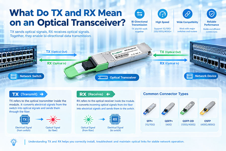
An optical transceiver is an electronic and optical component that performs bidirectional signal conversion. Its transmitter converts electrical data from the host device into optical signals, while its receiver converts incoming light into electrical signals for the host.
Optical transceivers are commonly installed in network switches, routers, servers, network interface cards and optical transport equipment. They provide the optical interfaces needed to connect these devices through fiber-optic cables.
Typical transceiver functions include:
Electrical-to-optical conversion: Converts electrical signals from the host into modulated light.
Optical-to-electrical conversion: Detects received optical signals and converts them into electrical signals.
Optical interface support: Provides a specified wavelength, fiber type, connector and transmission distance.
High-speed data transmission: Supports interfaces such as 1G, 10G, 25G, 100G, 400G and higher data rates, depending on the module.
Digital diagnostics: Selected modules provide DOM/DDM monitoring for temperature, voltage, TX power, RX power and other parameters.
Common optical transceiver form factors include SFP, SFP+, SFP28, QSFP+, QSFP28, QSFP-DD and OSFP. The form factor determines the package and host interface, while the optical type determines the fiber and transmission characteristics.
↓
Optical Transceiver
↓
Electrical Signal → Optical Signal
↓
Fiber-Optic Link
An optical transceiver generally does not operate as a complete standalone network connection device. It depends on a compatible host port to provide electrical connectivity, power, data processing and network functions.
2. What Is a Media Converter?
A media converter is a standalone networking device designed to convert signals between different transmission media or interfaces. A common application is converting copper Ethernet signals from an RJ45 port into optical Ethernet signals for transmission over fiber.
Media converters are widely used when network equipment has a copper Ethernet interface but the connection needs to extend over fiber. They can also support other conversion arrangements, including fiber-to-fiber interfaces and selected optical-to-electrical-to-optical applications.
A typical copper-to-fiber media converter includes:
RJ45 Ethernet port: Connects to a copper Ethernet device through twisted-pair cabling.
Fiber interface: Connects to an optical fiber link through a fixed optical port or an SFP/SFP+ slot.
Conversion circuitry: Performs the required electrical and optical interface conversion.
Power supply: Provides operating power to the standalone equipment.
Status indicators: LEDs commonly show power, link and activity status.
↓ RJ45 Cable
Media Converter
↓ Optical Interface
Fiber-Optic Link
↓
Remote Media Converter or Compatible Optical Device
Unlike a pluggable optical transceiver, a media converter can connect devices that do not have a native fiber-optic port. This makes it useful for extending existing Ethernet networks over fiber without replacing the original copper-interface equipment.
3. Optical Transceiver vs Media Converter: Main Differences
The most important distinction is their position in the network architecture. An optical transceiver is a signal-conversion component installed in a host device, while a media converter is a complete device that provides the interfaces and circuitry needed to bridge different media.
| Technical Feature | Optical Transceiver | Media Converter |
|---|---|---|
| Product Type | Optical communication component | Standalone networking device |
| Primary Function | Converts electrical signals to optical signals and vice versa | Connects different network media or interfaces |
| Installation | Installed in a compatible host port | Installed as an independent device |
| Typical Interfaces | Electrical host interface and optical connector | RJ45 Ethernet, fixed fiber port or SFP/SFP+ slot |
| Power Source | Usually powered by the host equipment | Normally requires a separate power supply |
| Network Processing | Usually provides the physical optical interface; depends on host for network services | Performs media conversion and may provide additional functions depending on model |
| Optical Interface | Built into the transceiver module | May be fixed or provided through a replaceable optical module |
| Typical Application | Fiber ports on switches, routers and servers | Copper-to-fiber Ethernet extension and industrial network connectivity |
| Replaceability | Usually replaceable within a compatible host port | The complete converter is replaced or serviced as a device; SFP-based models allow optical module replacement |
| Operating Features | Optical monitoring, wavelength and link specifications | May include link indicators, auto-negotiation, PoE, VLAN, management or redundant power |
These products are not direct substitutes in every application. A transceiver supplies an optical interface to compatible host equipment, while a media converter allows equipment with one media interface to communicate over another.
4. How Does an Optical Transceiver Work?
An optical transceiver contains both transmitter and receiver functions in one module. The two directions of communication operate through separate optical paths or through a supported bidirectional wavelength arrangement.
In the transmit direction, electrical data enters the module from the host interface. The transmitter circuitry drives a laser or other optical source, producing a modulated optical signal that travels through the connected fiber.
In the receive direction, a photodetector converts incoming optical signals into electrical current. The receiving circuitry processes the signal and delivers electrical data to the host.
↓
Transmitter Circuit and Optical Source
↓
Fiber-Optic Signal
↓
Photodetector and Receiver Circuit
↓
Host Electrical Data
The module's optical characteristics determine which fiber and network link it can support. These include transmit power, receiver sensitivity, wavelength, modulation, connector type, data rate and rated transmission distance.
For example, a 10G SFP+ LR transceiver and a 10G SFP+ SR transceiver have the same general package family and data-rate class, but they use different optical interfaces and fiber types.
5. How Does a Media Converter Work?
A conventional Ethernet media converter receives electrical Ethernet signals from a copper interface and converts them into optical signals for fiber transmission. At the remote end, a compatible converter performs the reverse process.
For a copper-to-fiber connection, the operation typically follows this sequence:
The copper Ethernet port receives data from a connected network device.
The converter's electrical interface processes the incoming Ethernet signaling.
Its optical interface sends the corresponding data over the fiber link.
The remote converter receives the optical signal and converts it back to an electrical Ethernet interface.
The remote RJ45 port forwards the connection to the destination device.
↓
RJ45 Copper Connection
↓
Media Converter A
↓
Optical Fiber
↓
Media Converter B
↓
RJ45 Copper Connection
↓
Destination Network Device
Many basic Ethernet media converters operate primarily at the physical layer and pass Ethernet traffic transparently. Some advanced models provide additional functions such as rate conversion, link fault pass-through, management, VLAN features or optical-electrical-optical regeneration.
The exact conversion behavior depends on the device architecture. A simple media converter should not be assumed to provide routing, switching, protocol translation or traffic-management functions unless these capabilities are explicitly specified.
6. Can a Media Converter Contain an Optical Transceiver?
Yes. Some media converters use fixed optical interfaces, while others include an SFP or SFP+ slot that accepts a compatible pluggable optical transceiver.
This means the media converter and optical transceiver can work together in the same device. The converter provides the copper Ethernet interface and electrical-to-optical conversion platform, while the installed SFP module provides the specific optical characteristics of the fiber link.
| Media Converter Design | Optical Interface | Replacement Flexibility |
|---|---|---|
| Fixed Optical Port | Built-in SC, ST, FC or another specified connector | Optical wavelength and reach are fixed by the product model |
| SFP-Based Converter | Replaceable SFP slot | Compatible modules can be selected for different fiber types and reaches |
| SFP+ Converter | Replaceable SFP+ slot | Supports compatible higher-speed optical interfaces |
| Multi-Port Converter | One or more fixed fiber ports or pluggable slots | Depends on the individual interface and equipment design |
For an SFP-based converter, the installed transceiver must match the converter's supported data rate, optical interface, wavelength, fiber type and operating requirements. A physically compatible SFP module is not necessarily supported by every media converter.
7. Media Converter vs Optical Transceiver: Installation Differences
Installation is one of the clearest practical differences between the two products.
Optical transceiver installation: The module is inserted into a compatible SFP, SFP+, QSFP or other optical port on a network device. The host provides power and handles the electrical interface and network functions. The optical fiber is then connected directly to the transceiver.
Media converter installation: The device is placed between the copper Ethernet equipment and the fiber link. It normally requires a separate power connection and appropriate copper and optical cabling.
| Installation Item | Optical Transceiver | Media Converter |
|---|---|---|
| Equipment Requirement | Compatible switch, router, server or other host | Standalone converter plus connected network devices |
| Power | Supplied through the host port | Separate DC or other supported power input |
| Fiber Connection | Directly connected to the transceiver | Connected to the converter's fixed optical port or SFP module |
| Copper Connection | Provided by the host device separately | Often provided directly by the converter's RJ45 port |
| Additional Equipment | Usually no separate media conversion box is needed | May require a converter at each end if both endpoints use copper interfaces |
8. Data Rate and Transmission Distance
Both optical transceivers and media converters can support different data rates and transmission distances. These parameters must be checked independently for the two product types.
An optical transceiver's data rate is defined by its optical and electrical interface specifications. Its transmission distance depends on the optical design, fiber type, wavelength and link budget.
A media converter's data rate is defined by its supported copper and optical interfaces. Its maximum fiber distance depends on the converter's fixed optical interface or the SFP module installed in the device.
| Product Type | Common Speed Classes | Distance Factors |
|---|---|---|
| Optical Transceiver | 1G, 10G, 25G, 40G, 100G, 400G and higher, depending on form factor | Wavelength, fiber type, optical power budget and transceiver specification |
| Commercial Media Converter | 10/100M, 1G and selected 10G configurations | Fixed optical interface or installed SFP/SFP+ module |
| Industrial Media Converter | 100M, 1G and selected 10G configurations | Optical port design, fiber type, module specification and environmental conditions |
| PoE Media Converter | 100M, 1G and selected 10G uplink configurations | Optical interface, installed transceiver and supported link budget |
For example, a media converter with a 1000Base-X SFP interface can use a compatible 1G optical module. The actual reach could be different depending on whether the installed SFP is an SR, LR, BiDi or another optical variant supported by the converter.
The converter's Ethernet speed limit must also be considered. Installing a higher-speed optical transceiver does not increase the converter's supported copper or internal data rate.
9. Commercial vs Industrial Media Converters
Media converters are available in commercial and industrial versions. Their basic media conversion function may be similar, but their operating temperature, power supply, enclosure and installation features can differ significantly.
Commercial media converters are commonly installed in offices, equipment rooms, enterprise networks and indoor communication cabinets. They generally operate within a standard commercial temperature range and use compact desktop or rack-mounted designs.
Industrial media converters are designed for environments that may involve wider temperature fluctuations, vibration, electrical interference and limited access to equipment. Depending on the model, they may provide wider DC input ranges, redundant power, DIN-rail mounting and ruggedized enclosures.
| Feature | Commercial Media Converter | Industrial Media Converter |
|---|---|---|
| Installation Environment | Offices, buildings and indoor equipment rooms | Factories, transport systems and outdoor cabinets |
| Operating Temperature | Commonly commercial temperature ranges | Extended temperature range, depending on model |
| Power Input | Commonly compact DC adapters | Wider DC input and redundant power on selected models |
| Housing | Compact metal or desktop enclosure | Ruggedized metal enclosure |
| Mounting | Desktop or rack installation | DIN rail, rack or other supported industrial mounting |
| Typical Application | Enterprise Ethernet and campus fiber extension | Industrial automation, traffic monitoring and remote control networks |
10. What Is a PoE Media Converter?
A Power over Ethernet (PoE) media converter combines Ethernet copper-to-fiber conversion with power delivery over the copper Ethernet interface.
It allows a network device such as an IP camera, wireless access point or other compatible powered device to receive both data and electrical power through one Ethernet cable, while the network connection is extended over optical fiber.
↓ Fiber Uplink
PoE Media Converter
↓ RJ45 Ethernet + PoE Power
Powered Network Device
Depending on the model, PoE media converters can support different power levels, Ethernet speeds and optical interfaces. The PoE standard, maximum output power, input voltage and connected device requirements must all be checked before installation.
Not every media converter provides PoE. Standard media converters only convert the supported network interface unless power delivery is explicitly included in the product specification.
11. Can an Optical Transceiver Replace a Media Converter?
An optical transceiver can replace the optical interface function of a media converter only when the connected network equipment already has a compatible optical port and can perform the required network functions.
For example, if two switches both provide compatible SFP ports, installing matching optical transceivers at each end can establish a direct fiber link. A standalone media converter is generally unnecessary in this situation.
However, if a network device has only an RJ45 copper interface and no optical port, a standard optical transceiver cannot be inserted directly into that connection. A compatible media converter or another suitable fiber-enabled network device is needed.
| Network Situation | Suitable Solution | Reason |
|---|---|---|
| Two switches both have compatible SFP ports | Optical transceivers at both ends | Both devices already provide optical interfaces |
| One device has RJ45 only, the other has fiber | Compatible media converter or fiber-enabled switch | Provides the missing copper-to-fiber interface |
| Two copper-only devices need a fiber connection | Two matching media converters or suitable replacement network devices | Converts copper Ethernet to fiber at both ends |
| Industrial IP camera requires PoE and a fiber uplink | PoE media converter | Combines optical uplink connectivity and copper-side power delivery |
| Existing converter has an SFP slot and needs a different fiber reach | Compatible replacement SFP transceiver | Changes the optical interface while retaining the converter |
12. Common Applications of Optical Transceivers
Optical transceivers are used wherever a network device needs a fiber-optic communication interface. They are especially common in data centers, enterprise networks, telecom infrastructure and high-performance computing systems.
Data center interconnects: Connect switches, routers and servers through high-speed optical links.
Enterprise networks: Provide fiber uplinks between network switches and buildings.
Telecommunications: Support metro, access and long-distance optical transport.
AI and high-performance computing: Provide high-bandwidth optical connections for GPU and compute clusters.
WDM transport: Support CWDM and DWDM wavelength channels for fiber-capacity expansion.
PON access: Provide optical interfaces for GPON, EPON, XG-PON and XGS-PON equipment.
The transceiver is selected according to the host port, data rate, optical standard, wavelength, transmission distance and fiber type.
13. Common Applications of Media Converters
Media converters are useful when an existing Ethernet device needs to communicate through fiber without replacing its original copper interface.
Building-to-building links: Extend Ethernet connectivity between buildings over fiber.
Enterprise access networks: Connect copper-based devices to fiber backbones.
Industrial automation: Extend Ethernet connectivity across electrically noisy industrial environments.
Video surveillance: Provide fiber uplinks for IP cameras and remote monitoring equipment.
Traffic and transportation systems: Connect remote network devices through fiber over longer distances.
PoE access: Combine an optical uplink with power delivery for compatible remote devices.
Media converters can be useful in retrofit projects where replacing existing switches or endpoint equipment is more expensive or disruptive than adding an independent fiber conversion device.
14. How to Choose Between an Optical Transceiver and a Media Converter
The correct choice depends on the interfaces already available on the connected network equipment and the required network topology.
| Selection Requirement | Recommended Product | Selection Consideration |
|---|---|---|
| Both network devices have compatible optical ports | Optical transceivers | Match form factor, speed, wavelength and fiber type |
| Endpoint has an RJ45 port but needs fiber connectivity | Media converter | Match copper speed and optical interface |
| Existing converter has an SFP slot | SFP optical transceiver | Check converter compatibility and SFP specifications |
| Network operates in a harsh industrial environment | Industrial media converter | Check temperature, DC input, mounting and redundancy |
| Remote device requires PoE power and fiber connectivity | PoE media converter | Verify PoE standard and maximum power output |
| High-speed data center or AI network | Compatible high-speed optical transceivers or fiber-enabled switches | Check lane rate, optical reach, host support and FEC |
| Fiber-to-fiber regeneration or conversion | Compatible OEO or specialized media converter | Verify supported optical interfaces and conversion functions |
Before final selection, verify the Ethernet standard, port speed, fiber mode, optical wavelength, connector type, transmission distance, optical power budget and equipment compatibility. For managed or industrial deployments, also check management options, power requirements, temperature range and installation method.
15. C-LIGHT Optical Transceiver and Media Converter Products
C-LIGHT provides optical transceivers and media converters for different fiber network applications. The two product categories serve complementary functions: optical modules provide the optical interface for compatible host equipment, while media converters provide standalone copper-to-fiber or other supported interface conversion.
C-LIGHT Optical Transceivers
C-LIGHT offers optical modules across multiple data rates and form factors, including SFP, SFP+, SFP28, QSFP+, QSFP28, QSFP-DD and OSFP. Product options cover short-reach multimode, single-mode, BiDi, CWDM, DWDM and coherent optical applications.
These modules are suitable for compatible switches, routers, servers, network interface cards and optical transport systems that provide the required host interface.
C-LIGHT Commercial Fiber Media Converter
C-LIGHT commercial media converters provide bidirectional conversion between copper Ethernet and fiber interfaces. The listed product configurations include 10/100/1000Base RJ45 ports with fixed SC, ST or FC optical interfaces, as well as SFP-based models.
The CL-M3011 series includes 1×RJ45 10/100/1000Base and 1×1000Base optical configurations. Selected compact commercial models specify a maximum power consumption of 3W and an operating temperature range of 0°C to 55°C.
C-LIGHT Industrial Fiber Media Converter
C-LIGHT industrial media converters are designed for fiber and copper Ethernet connectivity in industrial environments. The product family includes 100Base-X, 1000Base-X, SFP and selected 10G SFP+ configurations.
Selected models provide 12–48VDC power input, compact aluminum enclosures and an operating temperature range of -40°C to 75°C. Model-specific options include RJ45 interfaces, fixed SC fiber ports and SFP slots.
C-LIGHT Industrial PoE Media Converter
C-LIGHT industrial PoE media converters combine fiber Ethernet connectivity with power delivery over RJ45 ports. Depending on the model, configurations support 100Base-X, 1000Base-X or SFP/SFP+ optical interfaces, with different PoE output levels.
Selected configurations support 30W, 60W, 90W and higher PoE power options. Actual output power, input voltage and port count must be checked for the selected model.
When selecting a media converter, confirm the electrical port speed, optical port type, supported fiber standard, SFP compatibility, power input and operating environment. For transceivers installed in SFP-based converters, the module and converter must support the same optical interface and data rate.
16. Conclusion
An optical transceiver and a media converter perform related but different functions in fiber-optic networks. An optical transceiver is a module that converts electrical data into optical signals and incoming optical signals back into electrical data. It is normally installed in a compatible switch, router, server or other host device.
A media converter is a standalone networking device that connects different transmission media, commonly copper Ethernet and optical fiber. It can use a fixed optical interface or a replaceable SFP module and may provide additional functions such as PoE, redundant power or industrial-grade operation.
When both endpoints already have compatible optical ports, transceivers are generally the direct solution. When existing equipment only provides copper Ethernet connectivity, a media converter can provide the required fiber interface without replacing the entire network device.
The final selection should be based on port type, data rate, fiber compatibility, wavelength, transmission distance, power requirements and host-device support.
Looking for optical transceivers or fiber media converters?
Contact C-LIGHT for SFP optical modules, commercial and industrial media converters, PoE conversion equipment and fiber connectivity solutions.
 >

 >
 >
 >
 >
 >
 >
 >