TEL:+86 132 6656 7067




1. Introduction
High-speed optical transceivers used in 400G, 800G, and 1.6T networks require more than basic link-up testing. Qualification evaluates optical performance, electrical signal integrity, thermal behavior, power consumption, reliability, interoperability, and long-term operating stability.
2. What Is Optical Transceiver Qualification?
Optical transceiver qualification is a structured testing process used to verify that a module meets defined performance, reliability, environmental, and interoperability requirements. It normally covers both module-level measurements and complete host-to-host link testing.
3. Why Qualification Matters
A transceiver can establish a link and still have insufficient optical margin, excessive errors, unstable thermal behavior, or poor interoperability. Qualification helps identify these issues before large-scale deployment or mass production.
4. What Should Be Qualified?
| Area | Typical Tests |
|---|---|
| Optical Transmitter | Power, wavelength, eye quality, TDECQ, OMA |
| Optical Receiver | Sensitivity, overload, BER |
| Electrical | Signal integrity, lane performance |
| Thermal | Temperature, power, thermal stability |
| Environmental | Temperature, humidity, vibration, storage |
| Interoperability | Host, cable, fiber, firmware, FEC |
| Reliability | Temperature cycling and long-duration operation |
5. Qualification Starts With Requirements
Before testing begins, define the target data rate, optical architecture, reach, wavelength, fiber type, connector, host interface, operating temperature, power limit, and required standards. Qualification criteria should be established before collecting test results.
6. Identify the Optical Architecture
Qualification requirements depend on whether the transceiver uses SR, DR, FR, LR, ER, coherent, parallel, or WDM architecture. The optical technology determines which measurements and test conditions are relevant.
7. PAM4 Qualification
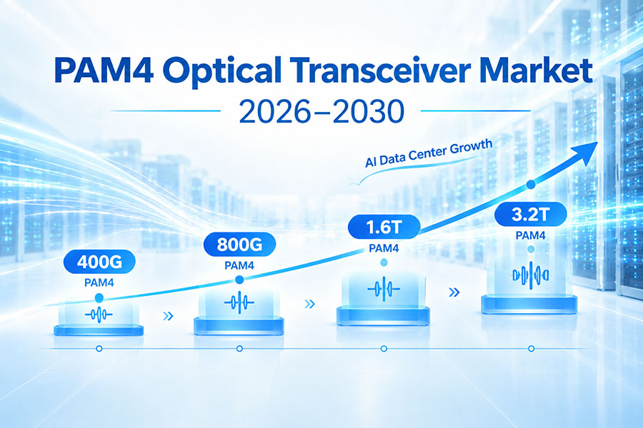
Modern 400G and 800G optical systems commonly use PAM4, while newer architectures are moving toward higher lane rates. PAM4 qualification requires careful evaluation of eye closure, noise, waveform quality, BER, and receiver tolerance.
8. Electrical Lane Qualification
Each high-speed electrical lane must maintain adequate signal quality between the host and optical engine. Channel loss, reflections, crosstalk, connector performance, and equalization should be evaluated as part of the electrical qualification.
9. Optical Transmitter Testing
Transmitter qualification verifies that the optical output meets the required power, wavelength, modulation quality, and error-performance limits. Testing should be performed under defined operating conditions and across the required temperature range.
10. Average Optical Power
Average optical power verifies the amount of optical energy launched by the transmitter. Power should be measured for each optical lane where applicable and checked against the product specification.
11. Wavelength Testing
Wavelength measurements confirm that the optical transmitter operates within the required wavelength range. WDM transceivers require additional attention because incorrect wavelength placement can affect channel compatibility.
12. Outer OMA
Outer Optical Modulation Amplitude evaluates the optical modulation strength of a PAM4 transmitter. It provides information about the available optical signal amplitude and is an important transmitter qualification parameter.
13. Extinction Ratio
Extinction ratio measures the relationship between different optical signal levels. It helps evaluate transmitter modulation quality and can identify abnormal laser or modulator behavior.
14. TDECQ Testing
TDECQ is an important performance metric for PAM4 optical transmitters. It evaluates transmitter eye closure after applying a defined reference equalization process and provides a more representative measurement than traditional NRZ eye-mask methods for PAM4 links.
15. Eye Diagram
The eye diagram provides a visual representation of the optical waveform. Qualification should examine eye opening, level separation, transition behavior, noise, and other waveform characteristics relevant to the selected signaling technology.
16. TECQ and Transmitter Waveform Quality
For applicable high-speed architectures, transmitter qualification can include additional transmitter eye-closure and waveform measurements. These tests help identify optical impairments that may not be visible from average power alone.
17. Overshoot and Undershoot
Excessive overshoot or undershoot can reduce signal margin and increase receiver stress. Waveform measurements should therefore be included when required by the applicable interface specification.
18. Optical Receiver Testing
Receiver qualification evaluates the minimum and maximum optical input levels that the module can tolerate while maintaining the required bit-error performance.
19. Receiver Sensitivity
Receiver sensitivity determines the minimum received optical power required to achieve the specified performance. Sensitivity testing is essential for validating the usable optical link budget.
20. Receiver Overload
Overload testing determines how the receiver behaves when the incoming optical signal becomes stronger than normal operating conditions. A qualified receiver should maintain stable operation within its specified input range.
21. BER Testing
Bit Error Rate is one of the most important qualification measurements. BER testing evaluates whether the optical link can maintain the required data integrity under defined signal and channel conditions.
22. Pre-FEC BER
Pre-FEC BER provides visibility into the quality of the transmission before forward error correction. It is particularly useful when evaluating the physical optical and electrical link margin.
23. Post-FEC Performance
Post-FEC performance indicates whether the complete system can maintain an acceptable error rate after error correction. Qualification should consider both corrected and uncorrectable errors when FEC is part of the architecture.
24. Optical Link Budget
A qualification program should verify that transmitter output, receiver sensitivity, fiber attenuation, connector loss, splice loss, and other passive losses leave sufficient optical margin for the intended link.
25. Stressed Receiver Testing
Stressed-receiver testing evaluates receiver behavior under controlled optical impairments. It helps determine whether the receiver maintains acceptable performance when the optical signal is less ideal than a clean laboratory signal.
26. Temperature Testing
Optical parameters can change with temperature. Qualification should measure module performance at relevant low, room, and high operating temperatures and verify that optical power, wavelength, BER, and electrical behavior remain within specification.
27. Thermal Stability
High-speed modules generate heat through DSPs, drivers, lasers, TIAs, and other components. Thermal qualification evaluates whether the module can maintain stable performance as internal temperature changes.
28. Power Consumption Testing
Actual module power should be measured rather than estimated only from individual component specifications. Typical and maximum power should be evaluated under representative operating conditions.
29. Power vs Temperature
Module power can change with temperature, optical output requirements, processing load, and device operating state. Measuring power across the operating temperature range provides a better basis for switch power and cooling design.
30. Host Electrical Testing
Qualification should evaluate the module together with the host electrical interface. The complete channel can include the switch ASIC, package, PCB, connector, module, and optical engine.
31. Signal Integrity Testing
Signal-integrity measurements can include insertion loss, return loss, crosstalk, eye quality, equalization performance, and lane-to-lane variation. These measurements become increasingly important at 100G-class and 200G-class lane rates.
32. Fiber and Connector Testing
Optical qualification should include the intended fiber type and connector system. Connector cleanliness, polarity, insertion loss, and optical return loss should be checked because physical cabling can strongly affect link performance.
33. MPO Qualification
Parallel optical modules using MPO or MTP interfaces require additional testing of fiber mapping and polarity. Every optical lane should be verified because one incorrect lane can cause partial or complete link failure.
34. LC and WDM Qualification
WDM modules using duplex LC interfaces require wavelength, insertion loss, optical power, and channel isolation checks. The complete wavelength plan should be validated at both ends of the link.
35. Host Compatibility
A transceiver should be tested with the actual switch, router, NIC, or other host equipment targeted for deployment. Mechanical compatibility alone does not guarantee successful operation.
36. EEPROM and Vendor Coding
Host equipment may read module identification data before enabling the port. EEPROM content, vendor coding, part information, and management data should therefore be included in compatibility testing.
37. Management and Diagnostics
Supported management functions should be verified during qualification. Tests can include temperature, voltage, Tx power, Rx power, laser bias, alarms, identification data, and other diagnostic parameters supported by the module.
38. FEC and Link Configuration
FEC settings, lane configuration, breakout mode, speed selection, and other host parameters should be tested using the actual deployment configuration. Incorrect settings can appear as optical or hardware problems even when the physical link is healthy.
39. Interoperability Testing
Interoperability qualification should test the transceiver with different supported hosts, cables, fibers, and remote endpoints where required. Sustained traffic testing is more useful than a simple link-up test because it can expose errors that appear only under load.
40. Environmental Qualification
Depending on the target application, qualification may include temperature cycling, humidity exposure, vibration, shock, storage conditions, ESD, and other environmental tests. Requirements should match the intended deployment environment.
41. Reliability Testing
Reliability testing evaluates whether the module continues to meet its specifications after environmental and operating stress. Optical power, BER, temperature, electrical behavior, and management functions should be checked before and after reliability tests.
42. Long-Duration Testing
Extended operation can reveal intermittent failures, thermal drift, optical degradation, or management instability that may not appear during short laboratory measurements. Long-duration traffic tests are particularly useful for high-density AI networks.
43. Manufacturing Qualification
Once the engineering design is qualified, production processes must be validated to ensure that mass-produced modules maintain the same performance. Automated optical and electrical measurements can improve test consistency and manufacturing throughput.
44. Production Test vs Design Qualification
| Test Type | Purpose |
|---|---|
| Design Qualification | Validate the product architecture |
| Reliability Qualification | Validate long-term robustness |
| Interoperability Test | Validate host and network compatibility |
| Production Test | Screen individual units |
| Final Inspection | Verify product quality and configuration |
45. Automated Qualification Testing
High-speed optical qualification generates large volumes of measurement data. Automated test systems can control instruments, run predefined sequences, record results, and compare measurements with pass/fail limits.
46. Failure Analysis
When a module fails qualification, engineers should identify whether the root cause is optical, electrical, thermal, mechanical, software, firmware, or manufacturing related. Repeating the same test without isolating the failure mechanism rarely provides enough information.
47. Common Qualification Failures
Typical failures include excessive TDECQ, insufficient optical power, poor receiver sensitivity, elevated BER, unstable temperature, excessive power consumption, incorrect EEPROM information, lane mapping errors, and host interoperability problems.
48. Qualification Documentation
A complete qualification report should record the sample configuration, hardware revision, firmware version, test equipment, test conditions, procedures, measured results, limits, failures, corrective actions, and final qualification status.
49. High-Speed Optical Transceiver Qualification Checklist
| Category | Key Items |
|---|---|
| Optical TX | Power, wavelength, OMA, ER, TDECQ, eye quality |
| Optical RX | Sensitivity, overload, BER |
| Electrical | Lane performance, signal integrity, channel loss |
| Thermal | Temperature, power, thermal stability |
| Fiber | Type, polarity, insertion loss, connectors |
| Management | EEPROM, diagnostics, alarms |
| Interoperability | Host, remote endpoint, cable, FEC |
| Reliability | Temperature cycling, environmental stress, long-duration operation |
50. Frequently Asked Questions
Q1. What is high-speed optical transceiver qualification?
Q2. Why is TDECQ important for PAM4 transceivers?
Q3. What optical parameters should be tested?
Q4. Why is temperature testing necessary?
Q5. Is link-up testing enough to qualify an optical transceiver?
Q6. What is the difference between design qualification and production testing?
Q7. Should optical transceivers be tested with actual switches?
Q8. Why is long-duration traffic testing important?
Q9. What should be tested on an MPO optical module?
Q10. What is the most important qualification principle?
51. Summary
High-speed optical transceiver qualification is a comprehensive process covering optical transmitter and receiver performance, PAM4 signal quality, electrical integrity, power, thermal behavior, fiber connectivity, management, interoperability, environmental stress, and reliability. For 400G, 800G, and 1.6T systems, measurements such as TDECQ, optical power, receiver sensitivity, BER, and electrical lane performance provide important visibility into link quality. Qualification should also include real host equipment, cables, fiber, FEC configuration, and sustained traffic because a module that performs well in isolation may behave differently in a complete network. A structured qualification process helps ensure consistent optical performance, reliable deployment, and stable production quality across high-speed data center and AI networking systems.
 >
>

 >
>
 >
>
 >
>
 >
>
 >
>
 >
>
 >
>