TEL:+86 132 6656 7067




1. Introduction
Linear Pluggable Optics (LPO) is an optical transceiver architecture developed to reduce power consumption, latency, and signal-processing complexity in high-speed networks. By removing or bypassing conventional DSP functions inside the optical module, LPO relies more heavily on the host ASIC and SerDes to manage the complete electrical and optical link. This makes LPO attractive for 800G and emerging 1.6T AI data center networks, but it also introduces tighter requirements for signal integrity and interoperability.
2. What Is LPO?
LPO stands for Linear Pluggable Optics. Unlike conventional retimed optical transceivers, LPO modules use a more linear electrical architecture and typically do not include a conventional DSP or CDR inside the optical module.
3. How Does LPO Work?
In a simplified LPO architecture, the host SerDes sends a high-speed electrical signal directly toward the optical module. A linear driver converts the electrical signal into an optical signal on the transmit side, while the receiver uses a photodetector and TIA to convert the optical signal back into an electrical signal.
4. Basic LPO Signal Path
Host ASIC / SerDes → Electrical Channel → Linear Driver → Optical Engine → Fiber → Optical Engine → TIA → Electrical Channel → Remote Host SerDes
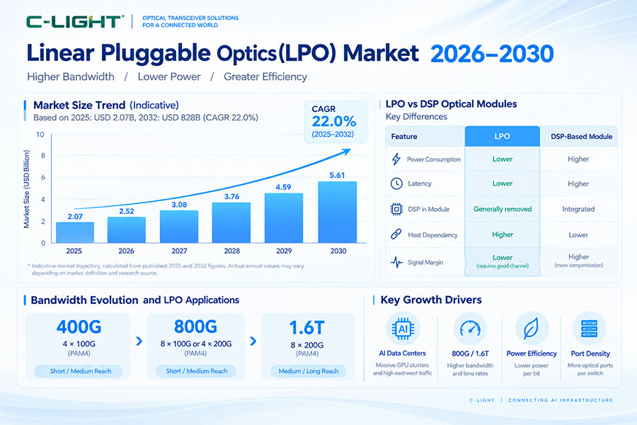
5. LPO vs Retimed Optics
| Parameter | LPO | Retimed Optics |
|---|---|---|
| Module DSP | Normally removed or bypassed | Typically included |
| Module CDR | Normally not required | May be included |
| Power | Lower potential | Higher in many designs |
| Latency | Lower potential | Higher due to processing |
| Host SerDes Requirement | Higher | Lower relative dependence |
| Signal Integrity | More critical | More signal conditioning in module |
| Interoperability | More architecture dependent | More established |
6. Advantage: Lower Module Power
The most important advantage of LPO is the potential reduction in optical module power. Removing the DSP and associated processing circuitry eliminates one of the major power-consuming elements in many conventional high-speed optical modules.
7. Advantage: Lower Latency
LPO reduces signal-processing stages inside the optical module. This can shorten the processing path and reduce transceiver-level latency, which is particularly relevant to latency-sensitive AI and high-performance computing workloads.
8. Advantage: Lower Thermal Load
Lower electrical power normally means less heat is generated by the optical module. This can reduce the thermal load around high-density switch ports and provide additional flexibility for system-level cooling.
9. Advantage: Simpler Module Architecture
Removing the DSP and CDR can simplify the internal architecture of the optical module. Fewer active processing components can reduce component count and may simplify parts of the optical engine and module design.
10. Advantage: Lower Power per Bit
LPO is particularly attractive when evaluating power efficiency by bandwidth. As network speeds move from 400G to 800G and beyond, reducing module processing power can improve the amount of bandwidth delivered per watt.
11. Advantage: Potential Cost Reduction
Removing expensive high-speed DSP components can create opportunities for lower module cost. The actual cost advantage depends on optical components, manufacturing scale, testing, packaging, host ASIC requirements, and the complete network architecture.
12. Advantage: Higher Port Density
Reducing module power can help switch designers manage the thermal load associated with large numbers of high-speed optical ports. This can support higher port density within a fixed system power and cooling envelope.
13. Advantage: Less Module-Level Processing
Conventional retimed optics perform significant signal conditioning inside the transceiver. LPO moves more of this responsibility toward the host system, reducing the amount of digital processing performed at the module level.
14. Advantage: Host ASIC Integration
Modern switch ASICs already contain highly capable SerDes and signal-processing functions. LPO takes advantage of these capabilities by allowing the host to manage more of the complete electrical channel.
15. Advantage: Protocol Flexibility
LPO is primarily an electrical and optical interface architecture rather than a networking protocol. This allows LPO concepts to be applied to different high-speed networking environments when the host and optical interface are designed accordingly.
16. Advantage: AI Data Center Applications
AI workloads create large amounts of traffic between GPUs, NICs, switches, and storage systems. Lower power and latency can be valuable in these environments because thousands of high-speed links may operate simultaneously.
17. 800G LPO
800G is currently one of the main application areas for LPO. An 800G module commonly uses eight 100G-class electrical and optical lanes, although the exact implementation depends on the host and optical architecture.
18. 1.6T LPO
As networks move toward 1.6T, LPO concepts are being considered for even higher lane rates. At 200G-class lanes, the advantages of reducing module-level DSP power become potentially more significant, while electrical signal-integrity requirements become substantially tighter.
19. PAM4 and LPO
High-speed LPO implementations commonly use PAM4 signaling. PAM4 provides four signal levels and carries two bits per symbol, enabling high data rates while increasing sensitivity to noise, loss, crosstalk, and waveform distortion.
20. Limitation: Host SerDes Requirements
The main limitation of LPO is that more responsibility is moved to the host. The host SerDes must handle the complete electrical channel effectively, including PCB traces, connectors, package transitions, module interfaces, and other channel losses.
21. Limitation: Electrical Channel Loss
High-speed electrical channels become increasingly difficult to manage as lane rates increase. Insertion loss, return loss, reflections, crosstalk, and inter-symbol interference can reduce signal margin and affect the performance of an LPO link.
22. Limitation: Signal Integrity
Because LPO provides less signal regeneration inside the module, the quality of the complete electrical path becomes more important. PCB layout, connector design, package characteristics, cable construction, and host SerDes equalization must work together.
23. Limitation: Interoperability
Interoperability can be more challenging than with conventional retimed optics. The optical module, host ASIC, SerDes, electrical channel, firmware, FEC configuration, and remote endpoint may all influence whether an LPO link operates reliably.
24. Limitation: Reach
LPO is generally more attractive for relatively short optical links because the host electrical channel must maintain strong signal quality without the same level of module-level regeneration found in retimed optics. Longer optical reach can require different architectures.
25. Limitation: Link Robustness
A retimed optical module can regenerate or reshape signals inside the transceiver. LPO has less internal signal restoration, so changes in host channel quality can have a greater effect on the complete link.
26. Limitation: Host Dependency
The performance of an LPO module cannot be evaluated independently from the host. A module that performs well with one switch ASIC may not deliver the same margin with another electrical architecture.
27. Limitation: Qualification Complexity
LPO qualification must consider the complete electrical and optical link. Testing only the optical module may not reveal problems caused by the host PCB, connectors, SerDes settings, or channel loss.
28. Limitation: FEC Dependency
FEC can provide additional protection against transmission errors, but the exact FEC architecture depends on the system. LPO deployments must ensure that the selected FEC mode provides sufficient margin without creating unacceptable latency, overhead, or power requirements.
29. Limitation: Manufacturing Tolerance
At high lane rates, relatively small variations in PCB loss, connector characteristics, package design, cable construction, or optical performance can affect the final margin. LPO therefore places greater importance on manufacturing consistency across the complete link.
30. Limitation: Troubleshooting
LPO troubleshooting can require more system-level analysis. A link problem may originate from the optical module, host SerDes, PCB channel, connector, fiber, FEC configuration, firmware, or remote endpoint.
31. LPO vs LRO
| Feature | LPO | LRO / RTLR |
|---|---|---|
| TX Path | Linear | Retimed |
| RX Path | Linear | Linear |
| Module DSP | Removed or bypassed | Reduced |
| Power | Lower potential | Intermediate |
| Latency | Lower potential | Intermediate |
| Signal Robustness | More host dependent | Compromise between LPO and retimed optics |
32. Why LRO Is an Alternative
LRO, also known as retimed transmit and linear receive or RTLR, retains retiming in part of the signal path while using a linear receiver architecture. It provides a compromise between the low power of LPO and the signal-conditioning capability of fully retimed optics.
33. LPO vs Silicon Photonics
LPO and silicon photonics describe different aspects of optical design. LPO defines the signal-processing architecture, while silicon photonics defines an optical integration technology. A silicon photonic optical engine can be used in an LPO module.
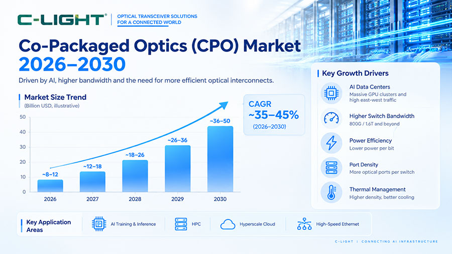
34. LPO vs CPO
LPO is a pluggable optical architecture, while CPO integrates optical engines much closer to the switching ASIC. Both aim to address power and signal-integrity challenges, but they do so at different levels of system integration.
35. LPO vs Traditional Pluggable Optics
Traditional retimed optics provide more signal processing inside the module, while LPO depends more heavily on the host electrical system. This creates a fundamental tradeoff between module-level processing and host-level signal management.
36. LPO Optical Technologies
LPO can be implemented with different optical technologies. Depending on the reach and product architecture, solutions can use VCSEL, EML, silicon photonics, or other optical engines. LPO itself does not define a particular laser technology.
37. LPO and VCSEL
VCSEL-based LPO is relevant to short-reach multimode applications. The relatively short optical distance makes it easier to target low-power linear architectures while maintaining the required optical performance.
38. LPO and Silicon Photonics
Silicon photonics can provide integrated modulators, waveguides, multiplexers, and photodetectors for LPO optical engines. The combination can support high optical integration while reducing module-level digital processing.
39. LPO and EML
EML-based optical engines can also be used in linear architectures. The EML provides the optical modulation function, while the electrical architecture determines how much signal conditioning is performed inside the module.
40. Thermal Management
Although LPO can reduce module power, thermal management remains necessary. Heat from the driver, TIA, laser, optical engine, and host ASIC must still be removed. Lower module power does not eliminate the need for a complete thermal design.
41. Air Cooling and LPO
Lower module power can make air cooling easier in high-density switches, but the overall cooling requirement depends on switch ASIC power, port count, inlet temperature, airflow, and rack-level thermal density.
42. Liquid Cooling and LPO
LPO and liquid cooling address different problems. LPO reduces certain module-level processing power, while liquid cooling removes heat from high-density systems. They can be used together when the host architecture supports both.
43. LPO in AI Clusters
AI clusters can benefit from low-power, low-latency optical links because communication occurs continuously between large numbers of accelerators and network devices. LPO is therefore particularly relevant to short-reach switch-to-NIC and accelerator networking.
44. Switch-to-Switch Applications
LPO can be used for short-reach switch-to-switch connectivity when the host electrical channel and optical distance remain within the supported architecture. Longer switch-to-switch links may require retimed optics or other optical solutions.
45. Switch-to-NIC Applications
High-speed switch-to-NIC links are an important LPO application. The optical module can reduce module-level processing while the host SerDes manages a larger portion of the complete channel.
46. GPU Networking
GPU clusters require high-bandwidth connections between compute nodes and network fabrics. LPO can provide a low-power optical option where short reach, host compatibility, and signal-integrity requirements are satisfied.
47. LPO Selection Factors
| Factor | What to Check |
|---|---|
| Host ASIC | Supported linear SerDes architecture |
| Lane Rate | 100G-class or 200G-class per lane |
| Reach | Optical and electrical channel limits |
| Power | Module power and system power |
| Optical Engine | VCSEL, EML, silicon photonics, or other architecture |
| FEC | Host configuration and error margin |
| Management | CMIS and diagnostic support |
| Interoperability | Host, module, cable, and remote endpoint |
48. When LPO Makes Sense
LPO can be attractive when reducing module power and latency is important, the host SerDes can manage the complete electrical channel, and the required optical distance is within the architecture's practical range. It is particularly relevant to high-density AI and data center networks.
49. When Retimed Optics May Be Preferred
Retimed optics can be more suitable when the electrical channel is challenging, greater signal regeneration is needed, interoperability requirements are broad, or the application requires reach and robustness beyond the practical LPO envelope.
50. Common LPO Deployment Mistakes
Common mistakes include treating LPO as a universal replacement for DSP-based optics, ignoring host SerDes performance, overlooking electrical channel loss, assuming every 800G switch supports LPO, comparing modules without testing the host platform, and focusing on module power without considering total system power.
51. LPO Troubleshooting Process
Start with module recognition and host compatibility. Then check electrical lane configuration, SerDes settings, FEC, optical power, fiber condition, temperature, lane-level BER, and remote-end configuration. For intermittent errors, inspect electrical channel margin and FEC counters rather than replacing the module immediately.
52. Frequently Asked Questions
Q1. What is the main advantage of LPO?
Q2. Does LPO use a DSP?
Q3. Does LPO always consume less power?
Q4. Does LPO reduce latency?
Q5. What is the biggest limitation of LPO?
Q6. Is LPO suitable for 800G?
Q7. Can LPO support 1.6T?
Q8. What is the difference between LPO and LRO?
Q9. Is LPO the same as silicon photonics?
Q10. Is LPO the same as CPO?
53. Summary
LPO provides a low-power and low-latency approach to high-speed optical connectivity by reducing or removing conventional DSP and CDR functions from the optical module. This can simplify the module architecture, lower thermal load, improve power per bit, and support high-density 800G and emerging 1.6T AI networks. The main limitation is that more responsibility moves to the host SerDes and electrical channel. As a result, signal integrity, electrical loss, FEC, interoperability, qualification, and troubleshooting become more important. LPO should therefore be selected according to the complete host-to-host architecture, including the switch ASIC, SerDes, optical engine, fiber, reach, thermal design, and network requirements. It is not a universal replacement for retimed optics, but one option within the broader evolution of high-speed optical interconnects.
 >
>

 >
>
 >
>
 >
>
 >
>
 >
>
 >
>
 >
>