TEL:+86 132 6656 7067




1. Introduction
800G optical transceivers provide much higher bandwidth than earlier generations, but the increase in speed also creates greater power and thermal-management challenges. Power consumption affects switch design, rack density, cooling capacity, operating cost, and the number of high-speed ports that can be deployed in a system.
2. What Is 800G Optical Transceiver Power Consumption?
Optical transceiver power consumption is the electrical power required by the module during operation. It includes the power used by signal-processing circuits, optical transmitters, receivers, drivers, monitoring circuits, and other internal components.
3. Why Power Matters at 800G
One 800G module may consume only a fraction of the total switch power, but a fully populated switch can contain dozens of high-speed optical modules. The combined module load can therefore become a significant part of the system's electrical and thermal budget.
4. Typical 800G Power Range
There is no single power value for every 800G transceiver. Current modules can operate across different power ranges depending on optical reach, DSP architecture, laser technology, connector configuration, and thermal design. Some commercial 800G modules are specified below 16W, while other architectures can require more power.
5. Main Components That Consume Power
| Component | Function | Power Impact |
|---|---|---|
| DSP | Signal processing and equalization | High in retimed designs |
| Laser / VCSEL / EML | Optical transmission | Medium to high |
| Driver | Drives optical modulator | Medium |
| TIA / Receiver | Amplifies received signal | Medium |
| CDR / Retimer | Signal recovery and retiming | Architecture dependent |
| Controller / PMIC | Management and power control | Low to medium |
6. DSP Is a Major Power Factor
In conventional retimed 800G optical modules, the DSP can be one of the largest power-consuming components. It performs functions such as equalization, clock recovery, signal conditioning, and other digital processing required to maintain link performance.
7. DSP Process Technology
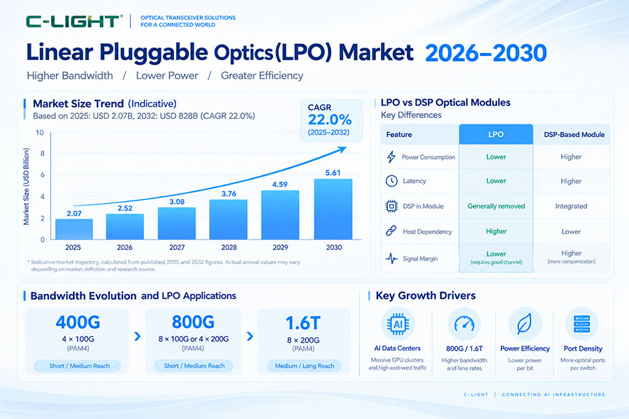
Advanced semiconductor process nodes can improve processing efficiency and reduce the energy required for a given amount of computation. However, process technology is only one part of the total module power budget.
8. Laser Power
The optical transmitter also contributes to module power. Laser efficiency, optical output requirements, temperature, wavelength, modulation architecture, and the required transmission distance all influence laser-related power consumption.
9. VCSEL-Based 800G
Short-reach 800G modules can use VCSEL arrays for multimode fiber transmission. VCSELs are well suited to short-reach applications, but the total module power still depends on the driver, receiver, DSP, and other electronics.
10. EML-Based 800G
EML-based architectures can be used for higher-performance single-mode optical transmission. Compared with short-reach VCSEL solutions, the optical requirements are different, which can affect the total power budget.
11. Silicon Photonics
Silicon photonics integrates multiple optical functions into a photonic integrated circuit. It can reduce some discrete optical complexity, but total module power still depends on the laser, drivers, receivers, DSP, and thermal architecture.
12. Electrical Lane Architecture
Common 800G architectures use eight 100G-class electrical lanes, although other implementations exist. Higher lane rates require careful electrical design and can increase the importance of channel loss, equalization, and connector performance.
13. PAM4 Signaling
PAM4 uses four signal levels to carry two bits per symbol and is widely used in high-speed 800G systems. Its efficiency enables high lane rates, but the smaller eye opening increases the need for signal conditioning and accurate electrical and optical design.
14. Optical Reach and Power
Reach has a direct effect on optical design. Short-reach modules can use relatively simple optical engines, while longer-reach modules require higher optical performance, stronger link budgets, and sometimes more complex signal processing.
15. 800G SR Power
Short-reach SR architectures generally use 850nm-class VCSELs and multimode fiber. Because the link is relatively short, the optical transmitter and receiver do not need the same long-distance performance as DR, FR, or LR solutions.
16. 800G DR Power
DR architectures use single-mode fiber and parallel optical channels for medium-reach connections. The optical components and link budget requirements differ from SR, which can affect power consumption.
17. 800G FR Power
FR architectures commonly use multiple wavelengths over single-mode fiber. WDM components, optical transmitters, receivers, and signal-processing requirements all contribute to the total module power.
18. 800G LR Power
LR modules are designed for longer single-mode links and generally require a larger optical budget. Their power consumption depends on the exact optical engine, DSP, laser, and receiver architecture.
19. Why Higher Reach Can Increase Power
Longer links require stronger optical performance and more tolerance to fiber and connector losses. This can increase transmitter, receiver, or signal-processing requirements, although reach alone does not determine module power.
20. Retimed 800G Optics
Retimed optical modules perform significant signal processing inside the transceiver. This can improve link robustness and interoperability with the host electrical interface, but the DSP and retiming circuitry contribute to module power.
21. LPO and 800G Power
Linear-drive Pluggable Optics reduces or bypasses some module-level DSP functions and relies more heavily on the host SerDes. This can significantly reduce module power in suitable implementations, but it also creates tighter electrical channel and interoperability requirements.
22. LPO Does Not Mean Zero Power
An LPO module still requires drivers, TIAs, lasers, receivers, control circuits, and other electronics. Removing a high-power DSP reduces one important power source but does not eliminate the module's electrical power requirement.
23. CDR and Retimer Power
Clock and Data Recovery or retiming functions can add additional processing power. Whether these functions are present depends on the module architecture and the signal-processing responsibilities assigned to the host system.
24. FEC and Power
Forward Error Correction is important for maintaining reliable high-speed links, but its exact implementation varies. FEC may be handled by the host ASIC, the optical module, or different combinations depending on the architecture.
25. Optical Receiver Power
The receiver side includes photodetectors and TIAs that convert weak optical signals into electrical signals. Receiver requirements can increase as optical power decreases or reach becomes longer.
26. Module Power vs System Power
Optical-module power should not be evaluated independently from switch power. The host ASIC, SerDes, fans, power supplies, and other components also consume energy. A lower-power optical module can help reduce system power, but the total benefit depends on the complete platform.
27. Example: 32 × 25W
If a switch contains 32 optical modules and each module consumes 25W, the optical modules alone would represent approximately 800W of electrical load. This simple example illustrates why transceiver power becomes increasingly important as port counts grow.
28. Power per Bit
Power per bit provides a more useful comparison across different bandwidth generations. An 800G module may use more absolute power than a 400G module while still achieving better energy efficiency if the power increase is smaller than the bandwidth increase.
29. 800G vs 400G Power
| Factor | 400G | 800G |
|---|---|---|
| Aggregate Bandwidth | 400Gbps | 800Gbps |
| Lane Rate | Lower generation | 100G-class common architecture |
| Signal Processing | Moderate to high | Higher requirements |
| Thermal Density | High | Higher |
| Power per Bit | Architecture dependent | Architecture dependent |
30. Thermal Management
Electrical power eventually becomes heat. A high-power 800G transceiver therefore increases the thermal load near the switch front panel. Heat sinks, airflow, chassis design, and component placement all affect whether the module can operate within its specified temperature range.
31. OSFP and Thermal Design
OSFP is widely used for 800G networking and supports high-power optical modules. The OSFP architecture can use integrated or other heat-sink arrangements depending on the product and host design.
32. OSFP-RHS
OSFP-RHS places the main heat-sink structure on the host cage rather than using the same mechanical arrangement as a standard integrated-heat-sink OSFP module. This can provide a different path for thermal integration in high-density systems.
33. Air Cooling
Air cooling remains widely used for 800G optical modules. The practical thermal limit depends on module power, switch airflow, inlet temperature, fan capability, heat-sink performance, and port density.
34. Liquid Cooling
Liquid-based cooling is becoming more relevant as AI systems reach higher rack and switch power densities. Cold plates, direct-to-chip cooling, and immersion cooling are different architectures, and standard air-designed optical modules should not automatically be assumed to be liquid compatible.
35. Power and Port Density
Port density multiplies the effect of per-module power. A switch with 64 high-power optical modules can have a much larger thermal challenge than one with only a few modules, even when the individual module specifications are identical.
36. Power and AI Data Centers
AI networks combine large numbers of GPUs, NICs, high-radix switches, and optical links. As the network fabric scales, optical-module power can become an important part of overall infrastructure planning.
37. Power and Rack Design
Higher optical-module power affects rack power distribution and cooling capacity. Network planners should consider switch power, module power, fan power, and facility cooling together rather than calculating only the transceiver specification.
38. Power and Operating Cost
Higher electrical power increases ongoing energy consumption. At large deployment scale, even a small difference in power per module can become significant when multiplied across many ports and operating hours.
39. Power and Reliability
Higher temperatures can accelerate component aging and reduce available operating margin. Effective thermal management helps keep optical and electrical components within their specified operating conditions and can support long-term reliability.
40. Power Measurement
Power should ideally be measured under defined operating conditions rather than using a single number without context. Traffic load, temperature, optical state, host configuration, and diagnostic functions can all influence actual power consumption.
41. Typical vs Maximum Power
Datasheets may specify typical and maximum power values. Typical power represents normal operating conditions, while maximum power is useful for system thermal and power-budget planning. System designers should use the appropriate value for each calculation.
42. Factors That Change Power
| Factor | Possible Effect |
|---|---|
| Transmission Distance | Can increase optical requirements |
| DSP Architecture | Major influence on processing power |
| Laser Type | Affects optical transmitter power |
| Temperature | Can change laser and electronic behavior |
| Traffic / Operating State | Can affect actual consumption |
| Diagnostic Functions | May add additional power |
| Cooling Design | Changes system-level energy use |
43. How to Reduce 800G Optical Module Power
Power can be reduced through more efficient DSPs, lower-power drivers and TIAs, improved laser efficiency, optical integration, optimized thermal design, and architectures such as LPO. The most effective approach depends on the target reach, host platform, and required signal margin.
44. Choosing a Low-Power 800G Transceiver
Start with the required transmission distance and host interface. Then compare module power, power per bit, optical architecture, DSP or LPO design, thermal solution, operating temperature, and compatibility. The lowest-power module is not necessarily suitable if it does not meet the required optical or electrical performance.
45. Common Deployment Mistakes
Common mistakes include comparing modules using maximum power only, ignoring power per bit, selecting long-reach optics for short links, overlooking switch airflow, and assuming that two 800G modules with the same bandwidth have the same power characteristics.
46. Troubleshooting High Module Temperature
If an 800G module operates near its thermal limit, check module power, inlet temperature, airflow direction, fan operation, heat-sink contact, adjacent-port loading, switch configuration, and optical diagnostics. Reducing airflow restrictions or replacing an unnecessarily high-power architecture can sometimes improve thermal margin.
47. Frequently Asked Questions
Q1. How much power does an 800G optical transceiver consume?
Q2. What consumes the most power in an 800G optical module?
Q3. Does LPO reduce 800G optical module power?
Q4. Does a longer-reach 800G module consume more power?
Q5. Why is power per bit important?
Q6. Does OSFP affect 800G power consumption?
Q7. Is air cooling enough for 800G optical modules?
Q8. Can liquid cooling be used with 800G optics?
Q9. Does lower optical-module power always mean better performance?
Q10. How can I reduce power in an 800G network?
48. Summary
800G optical transceiver power consumption depends on far more than the 800G data-rate label. DSP, laser technology, drivers, TIAs, CDR, optical reach, signaling architecture, temperature, and thermal design all contribute to the final power level. Retimed modules can provide strong signal conditioning but may consume more power, while LPO can reduce module-level processing power in suitable host architectures. As AI data centers deploy increasingly dense 800G switches, power per bit, port density, airflow, and cooling become critical design considerations. The right 800G transceiver should therefore be selected by balancing power, optical performance, reach, thermal requirements, interoperability, and the complete network architecture.
 >
>

 >
>
 >
>
 >
>
 >
>
 >
>
 >
>
 >
>