TEL:+86 132 6656 7067




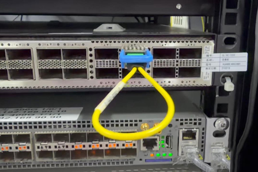
Loopback testing is a practical method for validating high-speed optical interfaces, transceiver operation, and link behavior on network equipment. For 400G Ethernet ports, digital diagnostic monitoring (DDM) provides additional visibility into optical transmit power, receive power, module temperature, supply voltage, and laser bias current. These measurements help engineers assess the physical interface during commissioning, troubleshooting, and interoperability testing.
This test case uses a Huawei switch interface, 400GE1/0/3, equipped with a Source Photonics 400GBASE-DR4 optical transceiver. The recorded diagnostic output provides a real equipment-level reference for examining module status and lane-level optical readings during loopback testing.
1. Test Equipment and Transceiver Information
The Huawei CLI output identifies the installed transceiver as a 400GBASE-DR4 module operating at a nominal wavelength of 1311 nm. The module uses an MPO 1×12 connector designation reported by the equipment and is identified by the vendor as Source Photonics.
| Parameter | Recorded Value |
|---|---|
| Network equipment | Huawei switch |
| Interface | 400GE1/0/3 |
| Transceiver type | 400GBASE_DR4 |
| Vendor | Source Photonics |
| Vendor part number | SPQ4EDRCDFM |
| Connector type reported by CLI | MPO 1×12 |
| Wavelength reported by CLI | 1311 nm |
| Reported transmission distance | 10,000 m over 9/125 µm SMF |
| DDM support | Yes |
| Manufacturing date | September 9, 2025 |
The reported transmission distance and connector information are transceiver identification fields from the device CLI. For deployment qualification, engineers should confirm the module's official datasheet, supported reach, fiber type, connector configuration, and Huawei platform compatibility. These fields alone do not establish that a particular cable or loopback arrangement is supported.
2. DDM Measurements During Testing
The diagnostic output reports four optical lanes for both transmit and receive power. It also provides module temperature, supply voltage, and laser bias current. These measurements are useful for checking whether the optical module is operating within its specified limits and whether the lane readings are consistent with the expected test configuration.
| Diagnostic Parameter | Lane 0 | Lane 1 | Lane 2 | Lane 3 |
|---|---|---|---|---|
| RX power (dBm) | 2.89 | 2.26 | 2.54 | 2.35 |
| TX power (dBm) | 3.35 | 2.92 | 2.78 | 2.75 |
| Bias current (mA) | 64.96 | 64.96 | 71.59 | 65.51 |
| Module-Level Parameter | Recorded Value |
|---|---|
| Temperature | 42.23°C |
| Supply voltage | 3.36 V |
The readings show that the interface is reporting optical measurements across all four lanes. The recorded RX power ranges from +2.26 dBm to +2.89 dBm, while TX power ranges from +2.75 dBm to +3.35 dBm. The module temperature is 42.23°C, and the reported supply voltage is 3.36 V.
Acceptance criteria: These values should be compared with the module manufacturer's specified TX power range, receiver operating range, temperature limits, voltage tolerance, and laser bias operating conditions. Without those limits, the measurements cannot independently establish whether the module passes or fails qualification.
3. Interpreting Transmit and Receive Optical Power
Transmit power represents the optical output reported by the transceiver, whereas receive power represents the optical signal detected at its receiver. During a loopback test, their relationship depends on the physical topology, the location of the loopback, the optical path, and the measurement point.
In a direct optical loopback configuration, transmitted optical signals are routed back toward a receiver through a compatible optical path. If the loopback uses an external fiber assembly, the measured receive level may be affected by connector insertion loss, fiber attenuation, adapter quality, and any intermediate optical components. The expected loss must be calculated from the actual test arrangement rather than assumed from the DDM values alone.
The reported receive power is higher than the reported transmit power on Lane 0, while the other three lanes show receive power below their respective transmit power readings. This does not automatically indicate a fault. The CLI's lane labels, internal optical paths, calibration tolerances, measurement accuracy, and loopback topology must be understood before drawing conclusions from TX-to-RX comparisons.
Optical power is expressed in dBm, a logarithmic unit referenced to 1 mW. A higher numerical dBm value represents greater optical power. Because the readings are transceiver-reported measurements, a proper optical qualification should also use the specified module limits and, when required, an independently calibrated optical power meter.
4. Lane-Level Diagnostics for 400GBASE-DR4
A 400GBASE-DR4 transceiver uses four parallel optical lanes. Checking the four lanes individually helps identify uneven optical levels, lane-specific issues, and potential inconsistencies in a parallel-fiber connection.
In this dataset, Lane 0 has the highest reported TX power and RX power. Lane 2 has the highest bias current at 71.59 mA, while Lane 1 has the lowest RX power at 2.26 dBm. The spread between lanes is not sufficient by itself to classify any lane as defective; the relevant manufacturer specifications and measurement tolerances are required.
| Parameter | Observed Range | Diagnostic Relevance |
|---|---|---|
| RX power | +2.26 to +2.89 dBm | Helps evaluate the received optical signal level on each lane. |
| TX power | +2.75 to +3.35 dBm | Helps assess optical output against the module's specified operating range. |
| Bias current | 64.96 to 71.59 mA | Provides insight into laser operating conditions; interpretation depends on the module design and specifications. |
For a complete 400G link validation, optical readings should be correlated with interface state, supported Ethernet mode, link negotiation or configuration, error counters, and traffic test results. DDM alone does not prove that all four lanes are carrying error-free traffic or that the complete 400G connection is operational.
5. Temperature and Voltage Monitoring
The module reports a temperature of 42.23°C and a supply voltage of 3.36 V. Both parameters are important when evaluating transceiver behavior under equipment operating conditions.
Temperature monitoring helps engineers identify thermal conditions that may affect optical performance or long-term reliability. Voltage monitoring provides an indication of the module's reported power supply condition. However, neither value should be assessed against a generic threshold when the module-specific operating range is available.
For repeatable testing, record these measurements after the module has stabilized and, where relevant, under different equipment loads or ambient conditions. Unexpected changes in temperature, voltage, bias current, or optical power should be investigated alongside interface logs and the module datasheet.
6. Practical Loopback Testing Procedure
A structured procedure helps separate physical-layer issues from configuration, compatibility, and traffic-level problems.
| Step | Test Action | Verification Objective |
|---|---|---|
| 1 | Identify the transceiver and interface. | Confirm the port, module type, vendor part number, and supported optical configuration. |
| 2 | Inspect and clean the optical connectors. | Reduce contamination-related insertion loss and intermittent optical contact. |
| 3 | Verify the loopback assembly. | Confirm connector type, fiber configuration, lane mapping, and compatibility with the intended test method. |
| 4 | Read the transceiver DDM values. | Record temperature, voltage, TX power, RX power, and bias current for all reported lanes. |
| 5 | Check the interface state and counters. | Determine whether the port is operational and whether errors or link instability are present. |
| 6 | Run traffic or a supported diagnostic test. | Verify data-path functionality, packet integrity, and error performance using an appropriate test method. |
| 7 | Compare the results with acceptance limits. | Document pass/fail status against the module specifications and test plan. |
Before connecting a loopback assembly, confirm that its optical routing is suitable for the transceiver and that the equipment supports the selected test mode. An optical loopback and an electrical loopback are different test arrangements and do not validate identical portions of the signal path.
7. What DDM Can and Cannot Confirm
DDM is a useful diagnostic source, but it should be treated as one part of a broader equipment validation process.
| DDM Can Help Confirm | DDM Cannot Establish on Its Own |
|---|---|
| Whether the module exposes optical and environmental diagnostic readings. | Whether the full link passes traffic without errors. |
| The reported TX and RX power for each monitored lane. | Whether all optical levels comply with specification without reference limits. |
| Changes in temperature, voltage, and laser bias current. | Whether the loopback assembly has correct physical lane mapping in every configuration. |
| Potential lane-level anomalies that merit further investigation. | Whether a module, cable, switch port, or configuration is definitively faulty. |
For final acceptance, combine DDM records with the actual interface state, device logs, error counters, traffic test results, and the relevant hardware specifications. If a discrepancy appears, replace or isolate one component at a time to narrow down the source of the problem.
8. Conclusion
The Huawei 400GE1/0/3 diagnostic output provides a useful reference for 400GBASE-DR4 transceiver monitoring during loopback testing. The installed Source Photonics module reports four lanes of TX and RX optical power, bias current, a temperature of 42.23°C, and a supply voltage of 3.36 V.
The readings support a lane-by-lane review of the transceiver's reported operating conditions, but they do not independently prove that the loopback test has passed. A reliable conclusion requires the correct loopback topology, manufacturer acceptance limits, interface and error-counter checks, and a suitable traffic or diagnostic test.
C-LIGHT provides optical transceivers, high-speed interconnect solutions, and compatibility support for data center and network equipment applications.
Contact C-LIGHT >
>

 >
>
 >
>
 >
>
 >
>
 >
>
 >
>
 >
>