 TEL:+86 132 6656 7067





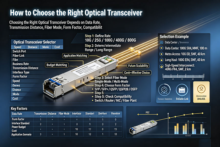
Selecting an optical transceiver requires more than matching a module's data rate to a switch port. The transceiver must also support the required transmission distance, fiber type, wavelength, connector interface, optical power budget, and host equipment. For high-speed networks, electrical interface specifications, lane mapping, FEC requirements, and thermal limits can be equally important.
A structured selection process helps network engineers avoid interoperability problems, unnecessary costs, and link performance issues across data centers, enterprise networks, telecom infrastructure, and AI clusters.
1. Match the Transceiver to the Required Data Rate
The first step is to identify the required link speed and confirm the data rate supported by the host port. Optical transceivers are available in multiple generations, from 1G and 10G to 100G, 400G, 800G, and 1.6T. A higher-speed module is not automatically compatible with a lower-speed port, even if the connector or cage appears similar.
| Data Rate | Common Form Factors | Typical Applications |
|---|---|---|
| 1G | SFP | Access switches, enterprise networks, and legacy infrastructure |
| 10G | SFP+ | Server connectivity, aggregation, and enterprise links |
| 25G | SFP28 | Data center servers and top-of-rack switches |
| 40G | QSFP+ | Data center aggregation and network uplinks |
| 100G | QSFP28 | Leaf-spine networks, core links, and data center interconnects |
| 200G | QSFP56, QSFP-DD and other supported designs | High-density switching and data center networks |
| 400G | QSFP-DD, OSFP | Cloud data centers, AI networks, and high-capacity aggregation |
| 800G | QSFP-DD800, OSFP | Large-scale AI clusters and high-bandwidth data center fabrics |
| 1.6T | OSFP and other emerging platform-specific designs | Next-generation AI and hyperscale data center interconnects |
These are representative form factors rather than universal compatibility rules. Availability and supported rates depend on the exact module specification and host platform. Always verify the port's supported operating modes before purchasing.
2. Choose the Correct Transmission Distance
The required reach determines which optical interface is suitable. Short-reach links commonly use multimode fiber or direct-attach solutions, while longer links generally use single-mode fiber and transceivers designed for the corresponding distance.
| Reach Category | Common Optical Types | Typical Fiber or Medium | Selection Consideration |
|---|---|---|---|
| Very short reach | DAC, AEC | Electrical copper cable | Confirm cable length, host compatibility, and power requirements |
| Short reach | SR, SR4, SR8 | Multimode fiber | Check OM3/OM4/OM5 support, lane configuration, and maximum reach |
| Intermediate reach | DR, DR4, FR, FR4 | Single-mode fiber | Verify the exact interface standard, wavelength arrangement, and reach |
| Long reach | LR, LR4, ER, ER4 | Single-mode fiber | Evaluate optical budget, dispersion, and rated transmission distance |
| Extended reach and transport | ZR, ZR+, coherent and DCO solutions | Single-mode fiber | Check line-system requirements, channel plan, power, and dispersion compensation |
Reach labels are not interchangeable across data rates or standards. For example, an SR module at one data rate may have a different maximum distance from an SR module at another rate. Select the exact interface specification rather than relying on the category name alone.
3. Select the Correct Fiber Type and Wavelength
Single-Mode Fiber
Single-mode fiber is widely used for campus networks, metro links, data center interconnects, and telecom applications. Common operating wavelengths include 1310 nm and 1550 nm, while CWDM and DWDM systems use defined wavelength channels for multiplexing multiple signals over the same fiber infrastructure.
Multimode Fiber
Multimode fiber is commonly used for short-reach connections inside data centers and enterprise buildings. The fiber grade, such as OM3 or OM4, affects supported distance and bandwidth. Many SR interfaces operate at 850 nm, but the actual wavelength and distance must be confirmed from the module specification.
4. Verify the Optical Power Budget
The optical power budget determines how much total loss a link can tolerate. It is calculated from the minimum transmitter output power and receiver sensitivity, using values specified for the relevant module and operating conditions.
Available optical power budget (dB) = Minimum Tx power (dBm) − Receiver sensitivity (dBm)
The total link loss includes fiber attenuation, connector loss, splice loss, and losses from any passive optical components. An engineering margin should also be reserved to account for maintenance, installation uncertainty, and future changes.
A sufficient budget is necessary but not sufficient for a reliable link. The selected transceiver must also meet its rated reach, receiver overload limits, dispersion requirements, and protocol-specific performance criteria.
5. Check the Host Port and Form Factor
The module must physically fit the host port and be supported by the switch, router, server NIC, or transport equipment. Common form factors include SFP, SFP+, SFP28, QSFP+, QSFP28, QSFP-DD, and OSFP.
Physical fit: Confirm the module or cable matches the port cage and connector interface.
Port speed: Check supported data rates, lane counts, and operating modes.
Host support: Verify the equipment's compatibility list, firmware requirements, and module coding policy.
Power and cooling: Check module power consumption, thermal limits, airflow, and port density.
Breakout support: For breakout links, confirm the host supports the required lane mapping, port configuration, and remote interface speeds.
Two modules with similar names or identical form factors may have different electrical interfaces or host requirements. Always check the specific product datasheet and platform documentation.
6. Confirm Compatibility Between Vendors
Optical transceiver compatibility depends on more than the optical connector. The module must conform to the required interface standard and operate correctly with the host platform's hardware, firmware, and configuration.
Before ordering, confirm:
Equipment manufacturer and exact model number.
Port type, port speed, and supported transceiver specifications.
Module coding requirements and any vendor-specific restrictions.
Wavelength, reach, connector, fiber type, and lane configuration.
FEC mode, link training, and breakout settings where applicable.
Diagnostic monitoring support and acceptable operating temperature.
For multi-vendor networks, test the transceiver on the intended equipment whenever possible. Compatibility should be verified at the actual operating speed and configuration, rather than inferred from a product label alone.
7. Choose Between Optical Transceivers, DAC, AOC, and AEC
Not every short-distance connection requires a separate optical transceiver and fiber patch cord. Direct-attach and active cable solutions can simplify cabling when the distance and interface requirements permit.
| Solution | Transmission Medium | Typical Use | Key Consideration |
|---|---|---|---|
| DAC | Passive copper, or active copper depending on design | Short server-to-switch and switch-to-switch connections | Length, cable thickness, reach, and host compatibility |
| AEC | Active copper with signal conditioning | Higher-speed copper connections requiring extended electrical reach | Power consumption, supported length, and platform qualification |
| AOC | Optical fiber with integrated active endpoints | High-speed connections where an integrated cable is preferred | Fixed cable assembly, optical reach, and endpoint compatibility |
| Optical transceivers plus fiber | Separate optical modules and fiber cabling | Flexible links across different distances and network areas | Module selection, fiber infrastructure, connector type, and optical budget |
DAC is often cost-effective for short connections, while AOC can provide longer reach and reduced cable weight compared with copper assemblies. AEC may extend electrical reach through active signal conditioning. Separate optical transceivers and fiber provide greater flexibility for structured cabling and longer-distance links.
8. Evaluate Power Consumption, Thermal Conditions, and Diagnostics
As data rates increase, module power consumption and thermal management become increasingly important. High-density 400G, 800G, and 1.6T deployments must account for switch airflow, module temperature limits, port density, and system power capacity.
Digital diagnostics monitoring (DDM/DOM) can provide information such as:
Module temperature and supply voltage.
Transmitter bias current and transmit optical power.
Received optical power.
Alarm and warning thresholds.
Diagnostic readings help identify optical power degradation, thermal issues, and potential module faults. However, diagnostic support and available parameters vary by product, and readings should be interpreted against the module's specifications and equipment documentation.
9. A Practical Optical Transceiver Selection Checklist
Identify the required data rate and protocol.
Confirm the host equipment model and port specifications.
Determine the link distance and required engineering margin.
Select the appropriate single-mode or multimode fiber interface.
Verify wavelength, connector type, polarity, and lane mapping.
Calculate the optical power budget and check receiver limits.
Confirm module coding, firmware, FEC, and interoperability requirements.
Evaluate power consumption, temperature range, and diagnostic support.
Check whether DAC, AEC, or AOC is a more suitable alternative.
Validate the final selection using datasheets and, where possible, testing on the target equipment.
10. Frequently Asked Questions
11.Conclusion
The right optical transceiver is determined by the complete link requirement, not by data rate alone. Data rate, reach, fiber type, wavelength, form factor, optical budget, equipment compatibility, and thermal conditions must all be considered together.
For reliable deployment, confirm the host specifications, validate the optical interface, and test interoperability before large-scale procurement. A correctly selected transceiver helps maintain stable link performance while balancing network capacity, power consumption, and deployment cost.
Need help selecting compatible optical transceivers?
Review connectivity options for Ethernet, InfiniBand, data centers, enterprise networks, and telecom applications.
Contact C-LIGHT >

 >
 >
 >
 >
 >
 >
 >














