TEL:+86 158 1857 3751


1. Introduction
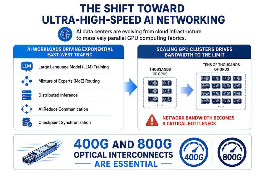
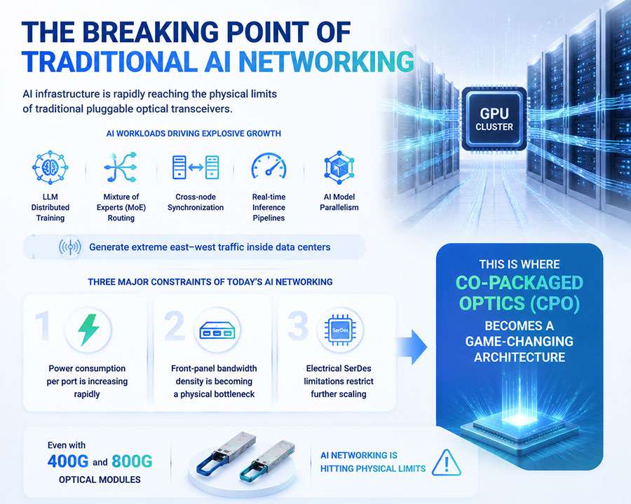
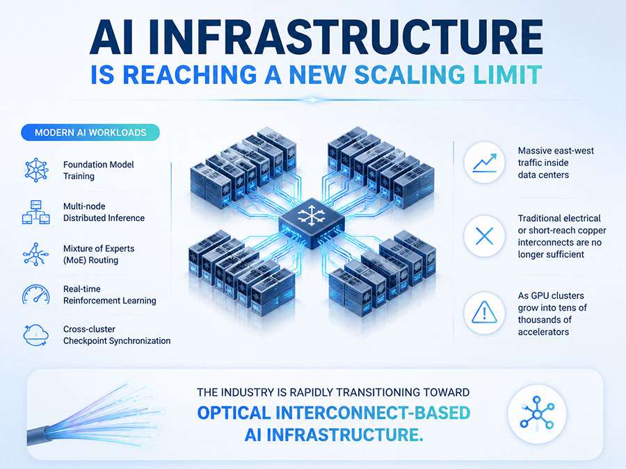
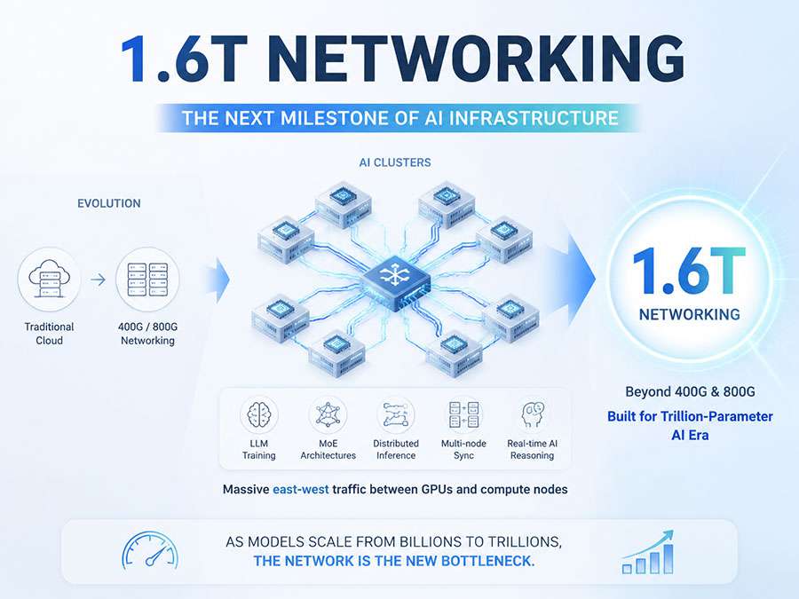
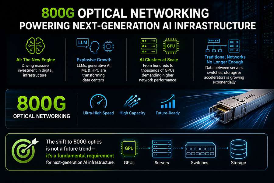
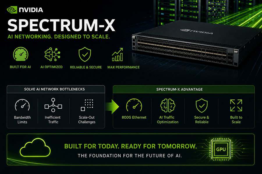
With the explosive growth of artificial intelligence (AI) large model training, high-performance computing (HPC) clusters, and cloud computing, global data center bandwidth demands are increasing at an unprecedented rate. 400G Ethernet has become the mainstream choice in data centers, while deployments of 800G and even 1.6T are rapidly accelerating.
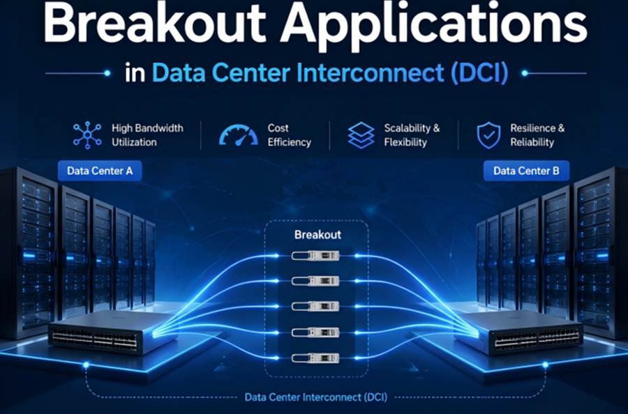
However, real-world data centers are not homogeneously operating at full speed. A large number of server NICs still run at 25G, 50G, or 100G, while switch ports are evolving toward 400G and 800G. This coexistence of high- and low-speed ports creates a heterogeneous architecture, giving rise to a critical interconnect technology: Breakout.
The core idea of Breakout is to physically split a high-speed port into multiple lower-speed channels. This enables efficient utilization of high-bandwidth ports while maintaining compatibility with existing lower-speed devices, allowing smooth network upgrades and efficient operations. By leveraging 400G/800G optical modules, DAC (Direct Attach Copper), AOC (Active Optical Cable), and MPO/MTP breakout fibers, enterprises can scale networks on demand without replacing all infrastructure at once.
In the AI computing era, an 800G port can be flexibly divided into 2×400G, 4×200G, or 8×100G links, offering unprecedented deployment flexibility for data center operators.
This article systematically explores the working principles of Breakout technology, its main implementation methods (covering both optical modules and cabling), and highlights C-LIGHT’s technical portfolio and representative products in this field.
2. Fundamentals and Architecture of Breakout
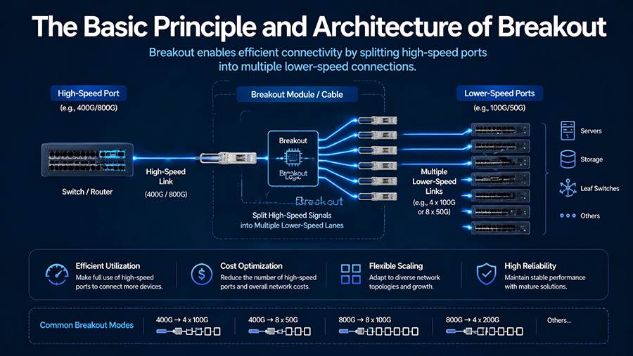
2.1 Physical Splitting of Electrical Channels
The theoretical foundation of Breakout lies in the parallel transmission architecture of high-speed Ethernet.
For example, 100G Ethernet defined by IEEE 802.3 is not a single “giant channel” but an aggregation of four 25G lanes. Similarly:
400G consists of 8 × 50G PAM4 electrical lanes
800G consists of 8 × 100G PAM4 electrical lanes
In Breakout mode, these parallel lanes are decoupled at the physical layer and routed to different endpoints. Notably, the optical module itself requires no firmware or configuration changes—the only change is the cabling.
For instance, a Leaf switch with 48 QSFP28 ports can support Breakout to split each 100G port into four 25G channels, enabling connectivity for up to 192 servers. This significantly improves port utilization and rack density.
2.2 From Point-to-Point to Multi-Point Topologies
In high-density Spine-Leaf architectures, Breakout plays a key role in “flattening” the network.
By using Breakout modules or cables on a single high-speed Spine port, it can be divided into multiple lower-speed links connecting to Leaf switches. Studies show that with Breakout-enabled designs:
The number of switches and optical modules can be reduced by up to 75%
Power consumption and cooling requirements are significantly lowered
3. Core Dimensions of Breakout: Modules and Cabling
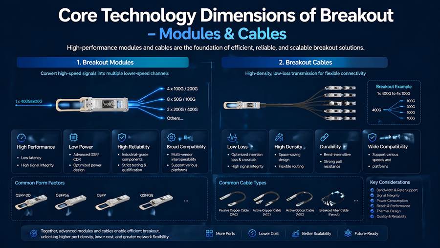
3.1 Optical Module-Based Breakout
Breakout based on pluggable optical modules is the most mainstream and flexible solution in data centers. A key advantage is that the same module can support multiple Breakout configurations simply by changing the fiber cable.
Taking an 800G DR8 module as an example:
800G Native Mode
Uses MPO-16 trunk fiber to deliver all 8 lanes to a single 800G port2×400G Breakout Mode
MPO-16 to 2×MPO-8 fiber splits lanes into two 400G links4×200G Breakout Mode
MPO-16 to 4×LC duplex fiber, each pair of lanes forms a 200G link8×100G Breakout Mode
MPO-16 to 8×LC simplex fiber maximizes port density
In multimode short-reach scenarios, a 400G SR8 module can connect to 8×50G devices using MPO-16 to 8×LC duplex harnesses, ideal for intra-rack ToR-to-server connectivity.
In single-mode scenarios, a 400G DR4 module connects to 4×100G devices via MTP-8 to 4×LC duplex fibers, providing a cost-effective upgrade path.
3.2 Types and Selection of Breakout Cables
Breakout cables are essential physical components and fall into three main categories:
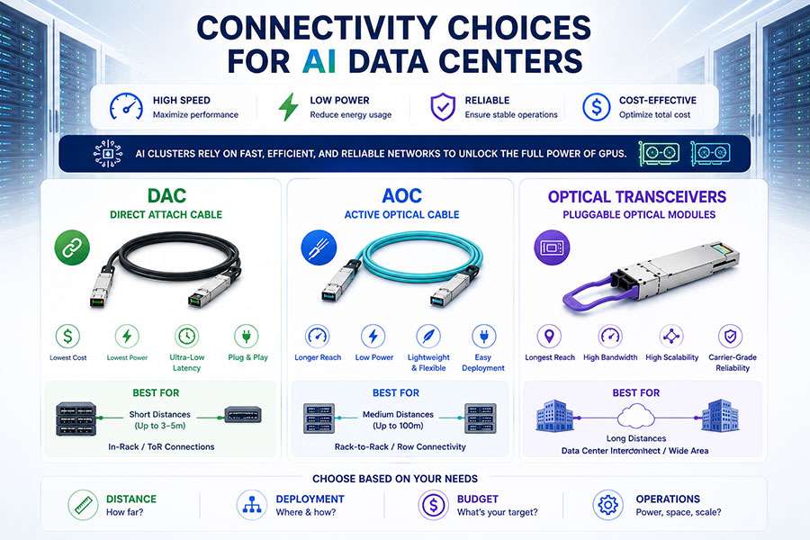
(1) Breakout DAC (Direct Attach Copper)
DAC consists of multiple Twinax copper cables:
One end: high-density connector (QSFP-DD/OSFP)
Other end: splits into multiple lower-speed connectors
Key features:
Passive (no additional power consumption)
Lowest cost and latency
Ideal for short distances (≤3–5 meters)
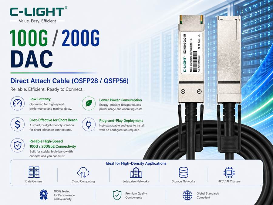
Example: A 3m QSFP-DD Breakout DAC can split a 400G/800G port into 4 links (4×100G or 4×200G).
(2) Breakout AOC (Active Optical Cable)
AOC integrates electro-optical conversion modules at both ends:
Uses fiber instead of copper
Supports longer distances (up to ~100m)
Better EMI immunity
Lower power consumption (~0.3W per 100G vs. ~1.5W for DAC)
Additional advantage:
Built-in DDM (Digital Diagnostic Monitoring) for real-time monitoring and predictive maintenance
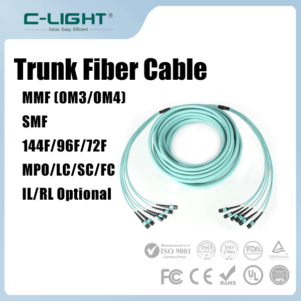
(3) MPO/MTP Breakout Fiber
The most flexible cabling solution:
One end: MPO/MTP (MPO-12, MPO-16)
Other end: LC/SC connectors
Advantages:
Supports 40G to 800G combinations
Low insertion loss (<0.35db typical="">
High reliability in dense cabling environments
4. C-LIGHT Breakout Product Portfolio
4.1 Company Overview
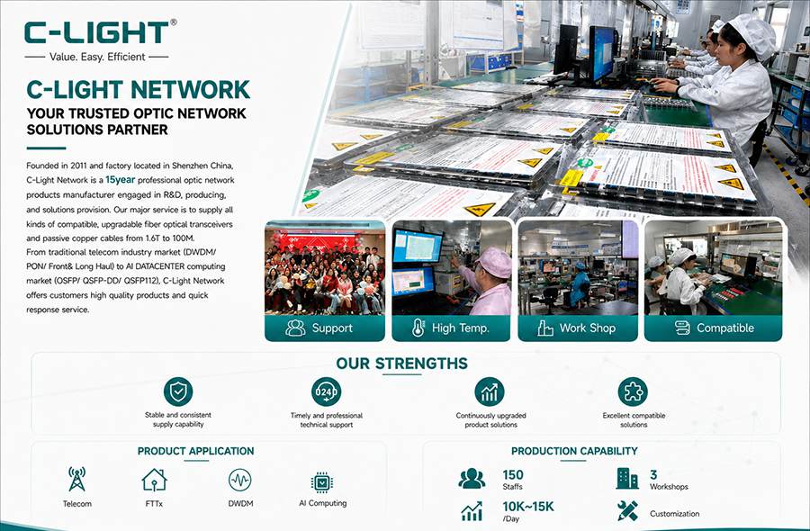
Founded in 2011, C-LIGHT has over 15 years of experience in optical communication. The company offers:
1,000+ optical module solutions
Full rate coverage: 800G to 10G
Over 50 R&D engineers
Applications across AI computing, data centers, telecom FTTx, and DWDM networks
4.2 Product Categories and Features
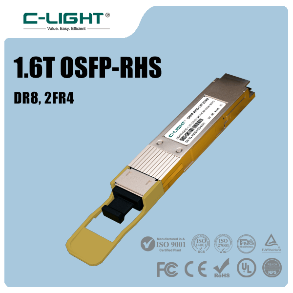
800G Optical Modules
Form factors: OSFP, QSFP-DD
Supports SR8, DR8, 2×DR4, 2×FR4, 2×LR4, ZR+
Enables distances from intra-rack to 450 km DCI
Key highlights:
Ultra-low latency (≤1μs)
Built-in Breakout (e.g., 2×400G DR4)
CS connector support for high-density panels
400G Optical Modules
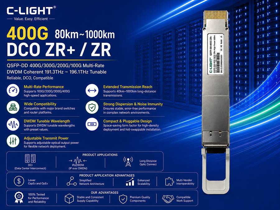
QSFP-DD and OSFP
Covers SR8 to ZR+
Native Breakout support (4×100G)
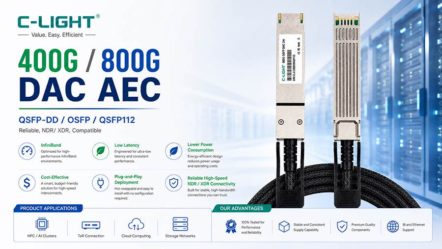
AOC and DAC
Full coverage: 800G–10G
AOC: ideal for GPU clusters
DAC: best cost efficiency for short reach
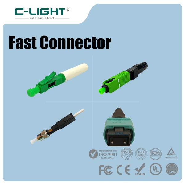
Breakout Fiber Assemblies
MTP/MPO to LC/SC/FC/ST
Low insertion loss (≤0.5dB)
High compatibility and reliability
Product Summary
| Category | Speed | Interface | Applications |
|---|---|---|---|
| 800G Modules | SR8/DR8/2×DR4/FR4/LR4/ZR+ | OSFP, QSFP-DD | AI clusters, hyperscale DC |
| 400G Modules | SR8/DR4/FR4/LR4/ZR | QSFP-DD, OSFP | Hybrid 100G/400G networks |
| AOC | 800G–10G | Multiple | GPU interconnect |
| DAC | 800G–10G | Multiple | Short-reach ToR |
| Fiber | MTP-LC etc. | MPO/MTP | Structured cabling |
5.Breakout Market Value
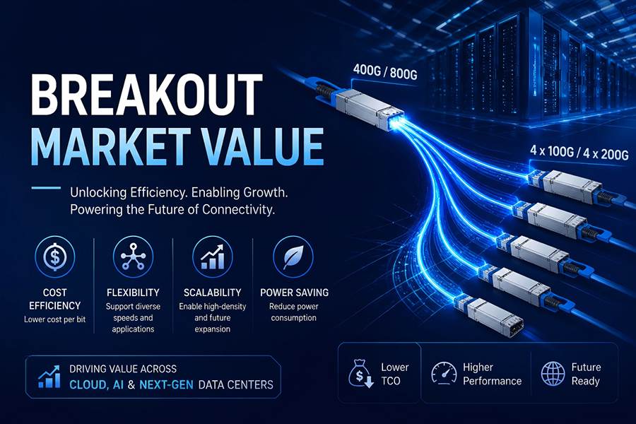
The global data center interconnect market is experiencing rapid growth driven by AI, hybrid cloud, and edge-to-core expansion. Deployment of 400G/800G interconnect solutions is accelerating.
Breakout technology acts as a “translator” between high-speed core and lower-speed access layers. It:
Protects existing infrastructure investments
Enables cost-effective bandwidth scaling
Supports gradual upgrades
Meanwhile, the industry is actively exploring Breakout solutions beyond 800G to meet future 1.6T-era demands.
With a comprehensive product portfolio from 800G to 10G, dual form-factor support (OSFP & QSFP-DD), and end-to-end solutions (modules + cables), C-LIGHT enables data center operators to deploy complex Breakout architectures within a single vendor ecosystem—reducing compatibility risks and simplifying operations.
From enterprise network upgrades to hyperscale AI clusters, Breakout technology combined with C-LIGHT solutions is becoming a foundational pillar for next-generation data center interconnects.
 >
>

 >
>
 >
>
 >
>
 >
>
 >
>