TEL:+86 132 6656 7067





An optical network link depends on much more than the physical condition of its fiber cable. A cable may have no visible damage and still fail to establish a connection because of excessive optical loss, contaminated connector end faces, incompatible transceivers, incorrect fiber polarity, or signal-quality problems. In high-speed Ethernet and data center networks, even a small deviation from the optical interface requirements can interrupt communication.
Effective troubleshooting requires checking the complete transmission path, from the transmitting module and optical connector to the receiving module and host equipment. The most useful diagnostic information often comes from TX power, RX power, module temperature, voltage, link status, and error counters rather than a visual inspection of the cable alone.
1. An Intact Fiber Cable Does Not Guarantee a Working Optical Link
Optical communication requires the transmitter to generate a suitable optical signal, the fiber path to carry that signal with acceptable loss, and the receiver to detect it within its specified operating range. The host equipment must also recognize and support the transceiver.
Fiber attenuation, connector loss, splice quality, bending, polarity, and optical power determine whether the signal reaches the receiver correctly.
Transmitter output, receiver sensitivity, wavelength, temperature, electrical interface, and module condition affect link operation.
Port configuration, supported transceiver types, firmware, speed settings, and FEC requirements can prevent a link from coming up.
BER, noise, dispersion, reflections, and insufficient optical margin can cause errors even when the link initially establishes.
2. Common Reasons an Optical Link Fails
Dirty or Contaminated Fiber Connectors
Connector contamination is one of the most common causes of optical link problems. Dust, oil, and other particles on the end face can obstruct the optical path, increase insertion loss, and create reflections. The connector may still fit securely into the transceiver, but its optical performance can be outside the required limits.
Inspect connector end faces with an appropriate fiber inspection microscope and clean them using approved tools before reconnection. Both sides of the mating interface should be inspected, including the transceiver receptacle where the equipment and procedure permit.
Excessive Insertion Loss
A link may fail when the total optical loss exceeds the available power budget. Loss can accumulate across fiber length, connector pairs, splices, patch panels, and passive components. A cable that looks intact may still contain poorly installed connections or excessive attenuation.
For example, if a transceiver has a minimum transmit power of -3 dBm and receiver sensitivity of -18 dBm, its available power budget is 15 dB. If the total link loss approaches or exceeds this value, the receiver may not receive sufficient optical power.
This is an illustrative calculation. Actual design must use the guaranteed limits for the exact transceiver and account for engineering margin and other applicable penalties.
Incorrect Fiber Type or Wavelength
Single-mode and multimode transceivers are designed for different fiber types and optical characteristics. A mismatch between the transceiver and cable can cause poor coupling or unreliable transmission. Wavelength incompatibility can also prevent the receiver from detecting the intended signal correctly.
For example, a typical 10GBASE-SR interface uses 850nm multimode optics, while 10GBASE-LR uses 1310nm single-mode optics. The fiber type and optical standard must match the intended link at both ends.
Incorrect Connector Polarity or Fiber Mapping
Duplex optical links require the transmitter at one end to connect to the receiver at the other. If Tx is connected to Tx and Rx to Rx, the optical path may be physically complete but communication will not work.
Parallel-optics systems require even more careful lane mapping. MPO cabling must match the transceiver's fiber positions, connector gender, key orientation, and polarity. A mechanically compatible MPO connector does not guarantee correct optical lane alignment.
Optical Transceiver Problems
A faulty or unsuitable optical module can cause a link failure even when the fiber path is functioning correctly. Possible causes include transmitter degradation, receiver faults, unstable operating conditions, or a module that does not support the required optical standard.
Digital Diagnostic Monitoring (DDM), also known as Digital Optical Monitoring (DOM) in some contexts, can provide useful information such as:
Transmit optical power (TX Power)
Receive optical power (RX Power)
Module temperature
Supply voltage
Laser bias current
Comparing these readings with the module datasheet can help identify abnormal operating conditions. DDM readings are diagnostic indicators and should not replace calibrated optical measurements when accuracy is required.
Host Compatibility and Port Configuration
A transceiver may be optically suitable but still fail to operate in a particular switch or router. The host port may not support the module, data rate, lane configuration, or required firmware behavior. Incorrect speed settings, FEC configuration, or port administration state can also prevent link establishment.
Check the equipment compatibility information, interface configuration, port status, and error logs. For high-speed modules, confirm that both ends use compatible Ethernet applications and FEC settings.
Excessive Bending or Hidden Fiber Damage
A cable can look normal externally while internal fiber damage or excessive bending increases attenuation. Tight bends, cable compression, poor routing, and repeated mechanical stress can affect optical performance without producing obvious external signs.
Inspect cable routing and bend conditions against the cable manufacturer's minimum bend-radius specification. Use optical loss measurements or OTDR testing to investigate suspected problems.
3. Optical Link Failure Symptoms and Possible Causes
| Observed Symptom | Possible Cause | Recommended Check |
|---|---|---|
| Link remains down | Incorrect polarity, unsupported module, incompatible wavelength, or insufficient RX power | Check port status, transceiver recognition, polarity, and optical power |
| RX power is too low | Dirty connectors, excessive attenuation, damaged fiber, or poor splice | Inspect and clean connectors; measure end-to-end insertion loss |
| Link frequently drops | Unstable module, temperature issue, marginal optical power, or host configuration | Monitor DDM values, logs, temperature, and port events |
| High BER or packet errors | Signal degradation, lane mapping issues, FEC mismatch, or optical margin problems | Check BER, FEC counters, lane status, and optical diagnostics |
| TX power appears normal but no link | Remote receiver issue, wrong polarity, host incompatibility, or remote port configuration | Check far-end RX power and equipment status |
| Link works over a short cable but fails over a longer path | Insufficient optical budget, excessive fiber loss, or distance beyond the supported reach | Calculate link budget and measure total path loss |
4. How to Troubleshoot an Optical Link Step by Step
A structured troubleshooting process helps isolate whether the problem originates from the cable plant, optical module, or host equipment.
Step 1: Check the Equipment and Port Status
Confirm that both ports are enabled and configured for the intended speed and interface. Check whether the switch recognizes the transceiver and whether the system reports compatibility warnings or module faults.
Step 2: Read DDM or DOM Information
Check TX power, RX power, temperature, voltage, and laser bias current where available. Compare the values with the transceiver's specified operating range. If the local TX power is normal but the remote RX power is low, investigate the optical path and the remote receiver.
Step 3: Inspect and Clean the Connectors
Inspect the connector end faces and clean them with suitable fiber-optic cleaning equipment. Check for scratches, contamination, damaged ferrules, and incompatible UPC/APC interfaces. Never look directly into an active fiber connector.
Step 4: Verify Fiber Type, Polarity, and Connection
Confirm that the installed fiber matches the transceiver's single-mode or multimode requirement. For duplex links, verify Tx-to-Rx connectivity. For MPO systems, confirm fiber positions, polarity, gender, and lane mapping.
Step 5: Measure Optical Loss
Use a calibrated light source and optical power meter, or an optical loss test set (OLTS), to measure end-to-end insertion loss. Compare the measured result with the link's acceptance limits and optical budget.
Step 6: Use OTDR to Locate Suspected Faults
If the loss measurement indicates a problem, an optical time-domain reflectometer (OTDR) can help locate high-loss events, reflective connections, bends, and suspected fiber breaks. OTDR results should be interpreted with suitable launch and receive fibers and the correct test settings.
Step 7: Check the Transceiver and Host Configuration
If the physical path passes testing, investigate the module and equipment. Where supported, test with a known-good compatible transceiver or port, one change at a time. Review FEC settings, lane status, firmware, and interface logs.
5. How to Interpret TX and RX Optical Power
TX and RX optical power are two of the most useful measurements for diagnosing an optical link. However, a normal reading at one end does not prove that the entire link is operating correctly.
| Diagnostic Reading | What It Indicates | What to Investigate |
|---|---|---|
| Normal local TX, low remote RX | The transmitted signal is not arriving at the remote receiver with sufficient power | Fiber loss, connectors, polarity, patch panels, and remote measurement accuracy |
| Low local TX | The transmitting module may be outside its expected operating range | Laser condition, module temperature, bias current, and module specifications |
| Normal RX power, high BER | Received power alone does not establish signal quality | Dispersion, reflections, OSNR where applicable, FEC, and lane-level errors |
| RX power above overload limit | The receiver may be receiving too much optical power | Maximum TX power, short-link loss, and approved attenuation requirements |
Receiver sensitivity and receiver overload are both important. A link can fail because the signal is too weak or because it exceeds the receiver's specified input range. Always compare the measured power with the exact transceiver's minimum and maximum operating limits.
6. Why Can an Optical Link Have Errors Even When RX Power Is Normal?
Optical power describes the amount of received light, not the complete quality of the transmitted data. A receiver may detect sufficient optical power while still experiencing signal distortion or excessive bit errors.
Chromatic dispersion: Different wavelength components travel at different group velocities, spreading optical pulses.
Polarization mode dispersion: Different polarization components experience different delays in the fiber.
Optical reflections: Connector interfaces or other discontinuities can introduce reflected light.
OSNR limitations: In amplified or coherent optical systems, optical signal-to-noise ratio can constrain performance.
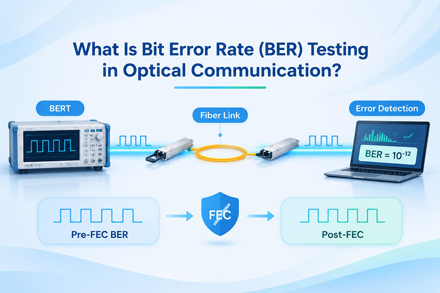
FEC mismatch or errors: Incompatible forward error correction settings or excessive pre-FEC errors can prevent reliable communication.
Lane-level problems: Parallel optical interfaces may have one or more degraded lanes even when aggregate power appears acceptable.
This is why high-speed link diagnosis should include BER, FEC statistics, lane-level diagnostics, and the relevant signal-quality measurements rather than relying on RX power alone.
7. Optical Transceiver Selection and Link Reliability
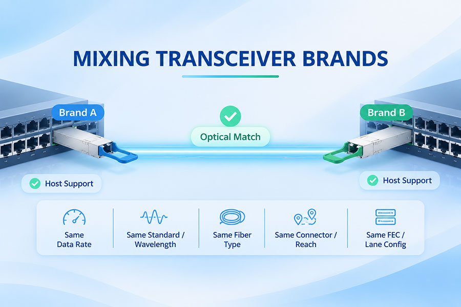
A stable optical link begins with selecting a transceiver that matches the network's optical and electrical requirements. Data rate, reach, fiber type, wavelength, connector, host compatibility, and operating environment all need to be considered.
Different 400G applications use different optical architectures. Check the specific SR, DR, FR, or other interface, including fiber type and connector requirements.
For high-density Ethernet platforms, the module must match the host's supported interface and the optical link design.
800G links require careful validation of optical lane configuration, power limits, connector mapping, and host compatibility.
Designed for supported high-bandwidth network platforms, with optical specifications selected for the intended reach and cabling architecture.
C-LIGHT provides optical transceiver options for data center and Ethernet networking applications. When evaluating a replacement module or a new link, confirm the exact equipment model, optical standard, transmission distance, fiber type, and connector interface to reduce compatibility and deployment risks.
8. How to Prevent Optical Link Failures
Consistent installation and maintenance practices can reduce avoidable link problems and improve network availability.
Inspect and clean fiber connectors before every connection.
Use the correct single-mode or multimode fiber for the optical interface.
Follow the specified bend radius and cable installation requirements.
Verify duplex polarity and MPO lane mapping before deployment.
Calculate the optical power budget and retain suitable engineering margin.
Use transceivers supported by the host equipment and intended network standard.
Monitor DDM readings, port events, BER, and FEC counters where available.
Perform optical loss testing after installation or major cabling changes.
Keep accurate records of module models, fiber routes, test results, and port assignments.
9. Conclusion
An optical link can fail even when the fiber cable is physically intact because successful transmission depends on the entire optical and electrical system. Connector contamination, excessive insertion loss, incorrect polarity, incompatible transceivers, host configuration, and signal-quality limitations can all interrupt communication.
The most effective troubleshooting method is to check equipment status, read optical diagnostics, inspect connectors, verify fiber compatibility, measure insertion loss, and investigate signal errors. By testing each part of the transmission path systematically, engineers can identify the actual fault instead of replacing an apparently intact cable without evidence.
Provide your equipment model, transceiver part number, TX/RX power readings, fiber type, and link distance for a more targeted technical evaluation.
Contact C-LIGHT >

 >
 >
 >
 >
 >
 >
 >