TEL:+86 132 6656 7067





Optical transceivers operate under changing electrical, thermal, and optical conditions. In high-speed Ethernet, InfiniBand, and data center networks, even a small change in module temperature, supply voltage, or laser operating current can provide useful information about the condition of an optical link.
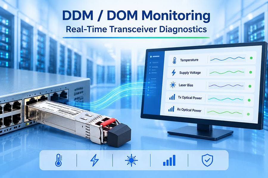
Digital Diagnostic Monitoring (DDM), also commonly called Digital Optical Monitoring (DOM), makes this information available through the transceiver's management interface. Network equipment can read internal measurements such as temperature, supply voltage, laser bias current, transmitter optical power, and receiver optical power without disconnecting the optical link.
These diagnostic values help engineers identify abnormal operating conditions, investigate link instability, and monitor module performance over time. Their value is greatest when readings are interpreted together rather than treated as independent pass-or-fail indicators.
1. What Are DDM and DOM in Optical Transceivers?
DDM and DOM refer to digital diagnostic functions built into supported optical transceivers. The module measures selected internal operating parameters and makes the readings available to the host device through a management interface.
In many product specifications, DDM and DOM are used interchangeably. The exact implementation depends on the transceiver form factor and its management standard. For example, SFP and SFP+ modules commonly use the SFF-8472 diagnostic interface, while many QSFP, QSFP-DD, and OSFP products use management structures based on the Common Management Interface Specification (CMIS).
| Diagnostic Parameter | What It Measures | Why It Matters |
|---|---|---|
| Temperature | Internal module temperature or specified temperature measurement point | Indicates thermal operating conditions. |
| Supply Voltage | Voltage monitored inside the transceiver | Helps identify abnormal module power conditions. |
| Laser Bias Current | Electrical current driving the transmitter laser | Helps track transmitter operating behavior. |
| TX Optical Power | Monitored transmitter output power | Provides an indication of local transmit performance. |
| RX Optical Power | Received optical power at the module input | Helps assess the incoming optical signal level. |
2. Temperature Monitoring: Understanding Module Thermal Conditions
Temperature is one of the most useful parameters in optical transceiver diagnostics. The laser, driver, receiver, DSP, and other electronic components generate heat during operation. As data rates and module power consumption increase, thermal management becomes increasingly important.
DDM temperature readings indicate the temperature measured at a sensor inside the module. Depending on the design, this measurement may represent the case or an internal component-related temperature. It should not automatically be treated as the ambient temperature around the transceiver.
What Can Abnormal Temperature Indicate?
Insufficient airflow: Restricted airflow or poor equipment ventilation may cause module temperature to rise.
High equipment density: Multiple high-power transceivers operating in a compact switch can increase local thermal load.
Cooling system changes: Fan speed, airflow direction, or cooling-system performance can affect module temperature.
High operating load: Some module designs have different thermal behavior depending on operating mode and power consumption.
Environmental conditions: High ambient temperature can reduce the available thermal margin.
A temperature reading should be evaluated against the specific module's operating-temperature range and configured warning and alarm thresholds. There is no single universal temperature limit suitable for every SFP, QSFP-DD, or OSFP transceiver.
3. Voltage Monitoring: Checking the Module Power Supply
Voltage monitoring measures the internal supply voltage available to the transceiver. Many optical modules use a nominal 3.3 V supply, although the actual electrical requirements depend on the module type and applicable specification.
Voltage monitoring is useful because the transceiver's laser driver, receiver circuitry, DSP, and control electronics depend on stable power. An abnormal reading may indicate a power delivery issue or an internal module condition that requires investigation.
Low Voltage
Voltage below the specified operating range may affect module initialization, transmitter operation, receiver performance, or overall stability.
High Voltage
Voltage above the supported range may indicate a host power issue or an abnormal electrical condition that needs attention.
Common Causes of Voltage Warnings
Power supply instability in the host switch or router.
Electrical power delivery limitations at the module port.
Abnormal host board operating conditions.
Module-specific power consumption or hardware problems.
Engineers should compare the reported value with the module's rated supply voltage and the host platform's supported electrical specifications. A voltage warning should not automatically be interpreted as a defective optical module.
4. Laser Bias Current: Monitoring Transmitter Operating Behavior
Laser bias current is the electrical current supplied to the optical transmitter's laser. It is one of the key diagnostic values used to observe the operating behavior of the transmitter.
The laser requires an appropriate drive current to produce optical output. The required current depends on the laser type, operating temperature, output-power target, and module design.
DDM monitoring allows the host system to read the transmitter's bias current and compare it with the module's expected operating range or historical baseline.
Why Laser Bias Current Matters
Operating-point visibility: The reading shows the current reported by the transmitter monitoring circuit.
Trend observation: Changes over time may help identify shifts in transmitter operating behavior.
Thermal correlation: Bias current may change with temperature and transmitter control behavior.
Fault investigation: Unusual readings, especially when combined with TX power changes or fault flags, can help narrow down a transmitter-side issue.
5. TX Power and RX Power: Monitoring Optical Signal Levels
TX and RX optical power readings provide information about the optical signal at the transceiver. They are particularly useful when investigating weak signals, unexpected power changes, and possible fiber-path problems.
TX Optical Power
TX power is the monitored optical output from the local transmitter. It can help identify changes in local transmit performance.
Low TX power may indicate a transmitter-side issue.
Unexpected changes may require checking the module's operating status.
The transmitter must be enabled for the measurement to be meaningful.
RX Optical Power
RX power is the optical signal level received by the local transceiver from the remote transmitter.
Low RX power may indicate excessive path loss or a remote transmitter issue.
High RX power may exceed the receiver's supported input range.
Readings should be compared with the module's receiver specifications.
How TX and RX Readings Help Isolate a Link Problem
| Local TX Power | Local RX Power | Possible Investigation Direction |
|---|---|---|
| Normal | Low | Check the remote transmitter, fiber path, connectors, patch panels, and optical attenuation. |
| Low | Normal | Investigate the local transmitter and the remote receiver's reported input level. |
| Low | Low | Check module operating conditions, host status, and both optical directions. |
| Normal | Normal | Continue investigating protocol, FEC, signal integrity, configuration, or intermittent faults. |
These patterns are diagnostic clues, not definitive fault conclusions. Optical power measurements do not directly reveal every type of signal-quality problem. A link can report normal TX and RX power while still experiencing high bit error rates, FEC errors, or other physical-layer issues.
6. Typical DDM Measurement Units and Data Interpretation
For SFP and SFP+ modules implementing the commonly used SFF-8472 internal calibration format, diagnostic measurements are represented using defined digital units. The host converts these raw values into engineering units for display.
| Parameter | Typical Internal Calibration Unit | Common Display Unit |
|---|---|---|
| Temperature | 1/256 °C per count | °C |
| Supply Voltage | 100 µV per count | V |
| Laser Bias Current | 2 µA per count | mA |
| TX Optical Power | 0.1 µW per count | mW or dBm |
| RX Optical Power | 0.1 µW per count | mW or dBm |
The values above describe the common SFF-8472 internal-calibration representation. Externally calibrated modules require the host to apply calibration coefficients. Other form factors and management interfaces may use different memory layouts, lane structures, or diagnostic reporting methods.
Converting Optical Power from mW to dBm
Optical power is frequently displayed in dBm because this logarithmic unit makes it easier to compare signal levels and calculate optical link budgets.
| Optical Power | Approximate dBm Value |
|---|---|
| 0.1 mW | -10 dBm |
| 0.5 mW | -3.01 dBm |
| 1 mW | 0 dBm |
| 2 mW | 3.01 dBm |
| 5 mW | 6.99 dBm |
When comparing TX or RX readings with a datasheet, make sure both values use the same measurement convention. For example, average optical power and optical modulation amplitude (OMA) are not interchangeable measurements.
7. DDM Alarm and Warning Thresholds
DDM-capable modules can provide warning and alarm flags when monitored parameters cross configured thresholds. These flags allow network equipment to identify abnormal conditions without requiring engineers to inspect every diagnostic value manually.
| Flag Type | Meaning | Typical Response |
|---|---|---|
| High Temperature Warning | Temperature exceeds the warning threshold. | Check airflow and monitor the trend. |
| High Temperature Alarm | Temperature exceeds the alarm threshold. | Investigate cooling and module operating conditions promptly. |
| Voltage Warning | Supply voltage approaches or crosses a warning limit. | Check the host power delivery and module specification. |
| Bias Current Alarm | Laser bias current crosses a configured alarm threshold. | Review TX power, transmitter status, and module diagnostics. |
| TX Power Alarm | Transmitter output is outside the configured limit. | Investigate the local transmitter and its operating state. |
| RX Power Alarm | Received optical power is outside the configured limit. | Check the incoming optical path and remote transmitter. |
Warning and alarm thresholds are defined for the specific module implementation. They should not be assumed to be identical across vendors, models, wavelengths, or optical reach categories.
8. DDM Monitoring Across SFP, QSFP-DD, and OSFP Modules
As optical interfaces have evolved from 1G and 10G to 400G, 800G, and higher data rates, module management has also become more sophisticated. The basic diagnostic concepts remain similar, but the number of monitored lanes and the management architecture can differ substantially.
| Form Factor | Common Management Approach | Diagnostic Considerations |
|---|---|---|
| SFP / SFP+ | SFF-8472 on supported modules | Commonly provides module temperature, voltage, bias, TX power, and RX power. |
| QSFP / QSFP28 | Form-factor-specific management interface | May provide module-level and lane-related diagnostics depending on implementation. |
| QSFP-DD | CMIS-based management on many products | Can expose per-lane TX and RX measurements and additional module status information. |
| OSFP | CMIS-based management on many products | Supports advanced monitoring structures for multi-lane high-speed modules. |
For high-speed transceivers, lane-level monitoring is particularly useful. A module may contain multiple optical transmit and receive lanes, and a single aggregate value may not reveal an issue affecting only one lane.
For example, an 800G module can report diagnostic information across multiple lanes. If one lane shows abnormal TX power or RX power while the others remain stable, the issue may be localized to that lane, its optical path, or its associated circuitry.
9. Common DDM Monitoring Problems and Troubleshooting
DDM values are useful only when the monitoring system reads, interprets, and displays them correctly. Incorrect calibration, unsupported fields, or differences between host software implementations can lead to misleading results.
DDM Data Is Not Available
Possible causes include a module without diagnostic support, an unsupported host interface, incorrect management access, or firmware limitations. Confirm that the transceiver supports DDM/DOM and that the host platform supports its management interface.
Temperature Readings Are Unusually High
Check the module's specified operating-temperature range, host airflow, equipment temperature, and nearby high-power modules. Compare the reading with other modules in similar positions before concluding that the transceiver is faulty.
TX Power Appears Normal but the Link Is Unstable
DDM TX power alone cannot confirm signal quality. Check RX power at the remote end, FEC statistics, error counters, link state, and the optical interface's supported transmission conditions.
RX Power Is Below the Expected Level
Inspect the optical path, connector condition, patching arrangement, fiber type, and remote transmitter output. Compare the measured level with the receiver sensitivity and optical budget of the exact module.
Laser Bias Current Changes Over Time
Compare the current reading with the module's historical baseline and TX power. Consider temperature and operating-mode changes. A bias-current trend is useful supporting evidence, but it is not sufficient by itself to diagnose laser degradation.
10. C-LIGHT Optical Transceivers and Diagnostic Monitoring
C-LIGHT provides optical transceiver solutions across multiple data rates and form factors for data center, enterprise, and high-performance computing networks. Diagnostic monitoring is an important consideration when selecting modules for equipment that requires operational visibility and remote troubleshooting.
400G QSFP-DD Optical Transceivers
Designed for high-bandwidth data center connectivity. When selecting a 400G module, verify the supported management interface, lane-level diagnostic availability, and host platform compatibility.
View 400G QSFP-DD Products800G OSFP Optical Transceivers
For 800G data center and AI network applications, module diagnostics can help monitor temperature, supply voltage, and optical performance across the supported lanes.
View 800G OSFP Products800G QSFP-DD Optical Transceivers
High-speed optical connectivity for compatible 800G platforms. Confirm the specific module's diagnostic functions and host management support before deployment.
View 800G QSFP-DD ProductsOptical Module Compatibility and Testing
Module selection should account for data rate, wavelength, reach, connector, power consumption, operating temperature, and management-interface requirements.
Discuss Your Application with C-LIGHTDDM/DOM functionality can vary by exact product model. Customers should confirm which diagnostic parameters are supported, whether measurements are reported per module or per lane, and which host platforms can access the information. Product-level specifications should be used for final qualification.
11. Conclusion
DDM and DOM monitoring provide important visibility into the operating condition of optical transceivers. Temperature indicates thermal conditions, voltage reflects the module's monitored power supply, and laser bias current provides insight into transmitter operation. TX and RX optical power readings add further information about the optical signal at each end of a connection.
For modern high-speed networks, these measurements support preventive maintenance, fault investigation, and module performance monitoring. However, they should always be interpreted against the exact transceiver specifications and management standard. Combining DDM readings with FEC statistics, error counters, link status, and optical power measurements produces a more reliable view of overall link health.
12. Frequently Asked Questions
They are commonly used as interchangeable terms for digital optical diagnostic monitoring. The exact implementation depends on the module's management interface and supported specification.
Common SFF-8472 diagnostic parameters include module temperature, supply voltage, laser bias current, TX optical power, and RX optical power.
No. Diagnostic support depends on the product design and specification. Confirm DDM/DOM support in the exact module datasheet before deployment.
DDM cannot directly identify connector contamination. However, a reduction in RX power may indicate additional optical loss. Connector inspection and cleaning, followed by appropriate optical testing, can help identify the cause.
No. Normal diagnostic readings do not guarantee error-free transmission. FEC statistics, BER, link counters, signal integrity, and protocol status may reveal problems that optical power monitoring cannot detect.
Many CMIS-based modules support lane-level diagnostics, but the available parameters depend on the specific module and management implementation.
Need Optical Transceivers with Diagnostic Monitoring?
C-LIGHT supports optical connectivity requirements across SFP, QSFP-DD, OSFP, 400G, and 800G product families. Contact our team to confirm module specifications, DDM/DOM functionality, and host platform compatibility.
Contact C-LIGHT >

 >
 >
 >
 >
 >
 >
 >